AIR CONDITIONING
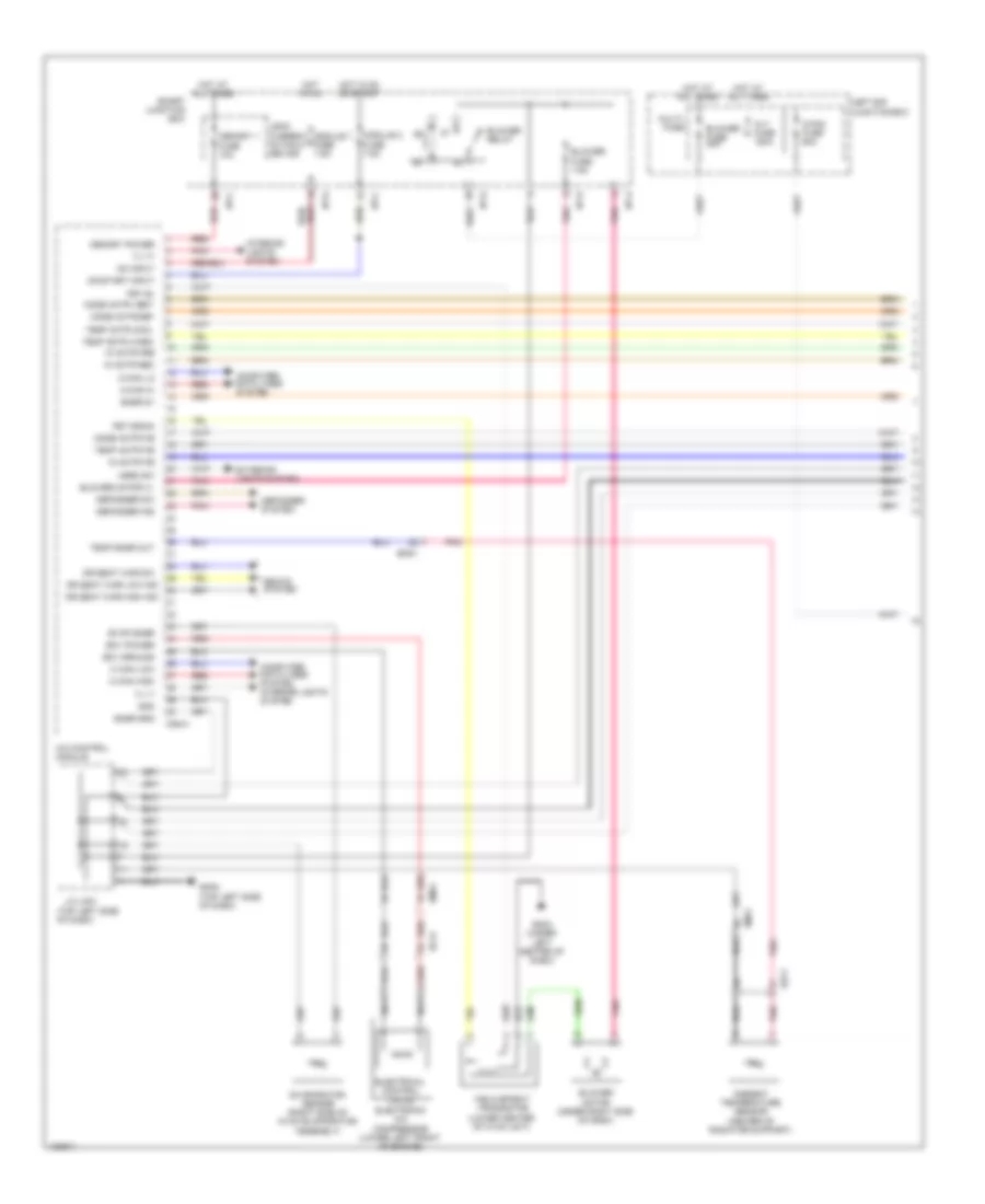
Automatic A/C Wiring Diagram (1 of 2) for Hyundai Genesis Coupe 2.0T R-Spec 2014

List of elements for Automatic A/C Wiring Diagram (1 of 2) for Hyundai Genesis Coupe 2.0T R-Spec 2014:
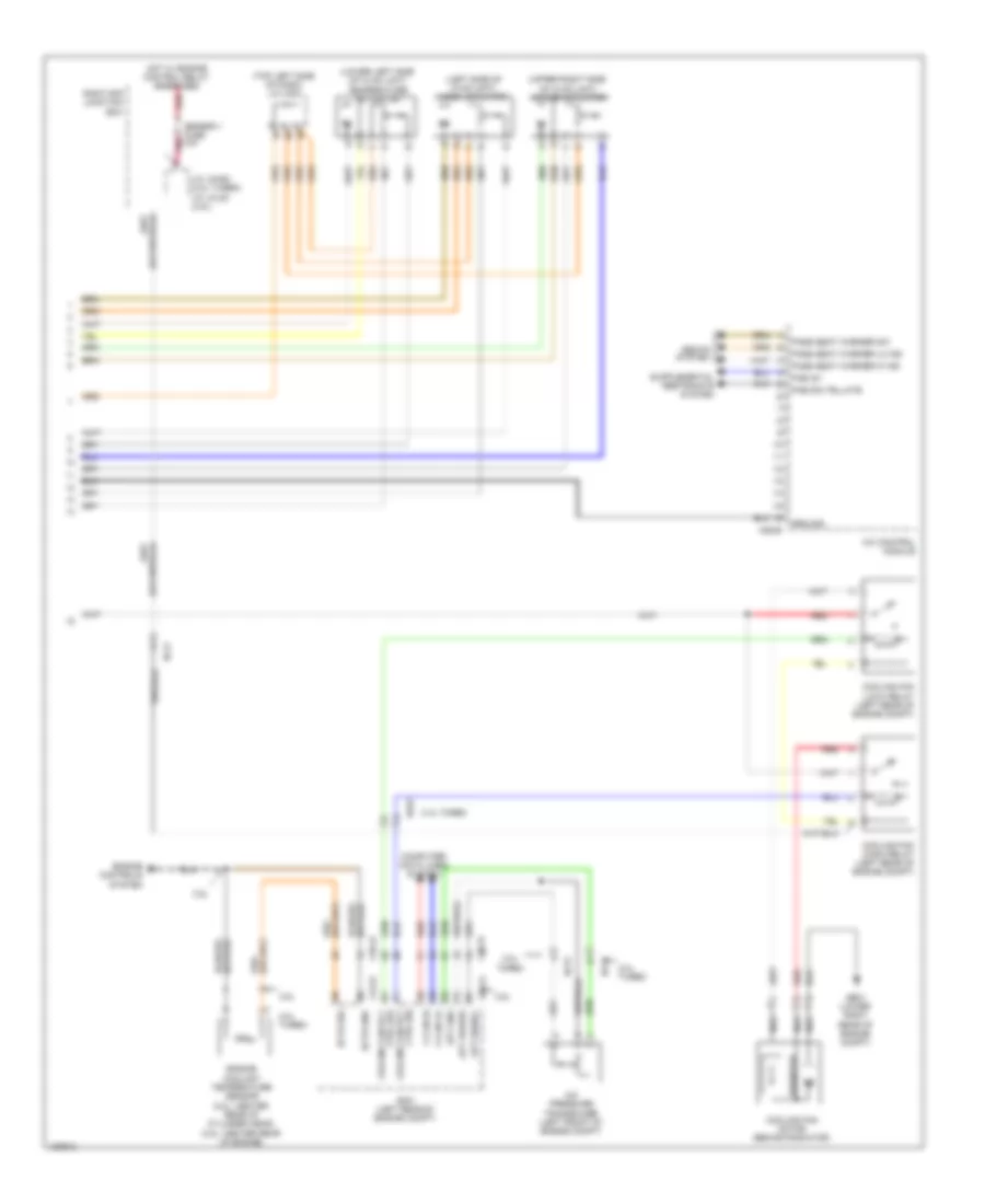
Automatic A/C Wiring Diagram (2 of 2) for Hyundai Genesis Coupe 2.0T R-Spec 2014
List of elements for Automatic A/C Wiring Diagram (2 of 2) for Hyundai Genesis Coupe 2.0T R-Spec 2014:
Manual A/C Wiring Diagram (1 of 2) for Hyundai Genesis Coupe 2.0T R-Spec 2014
List of elements for Manual A/C Wiring Diagram (1 of 2) for Hyundai Genesis Coupe 2.0T R-Spec 2014:
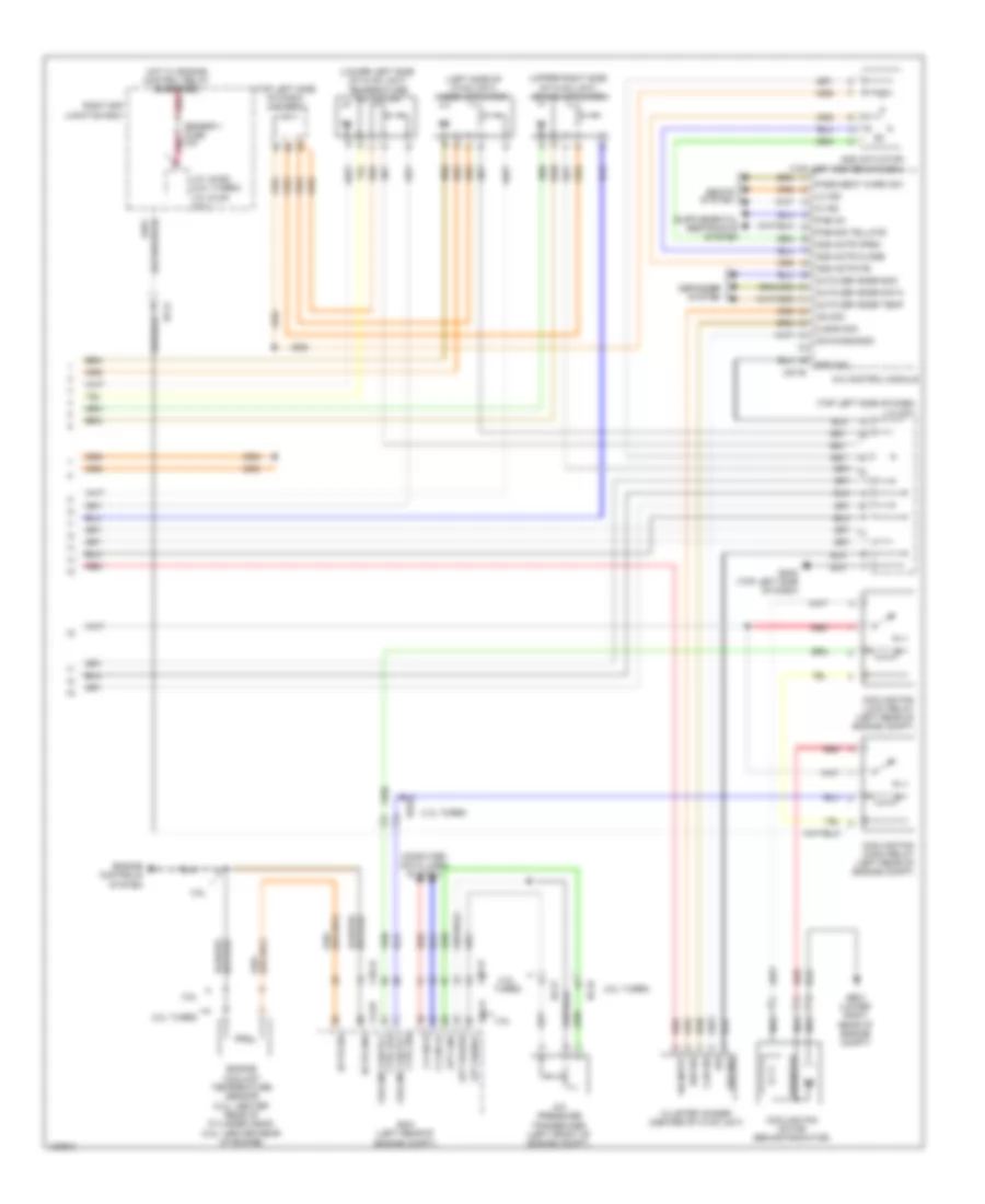
Manual A/C Wiring Diagram (2 of 2) for Hyundai Genesis Coupe 2.0T R-Spec 2014
List of elements for Manual A/C Wiring Diagram (2 of 2) for Hyundai Genesis Coupe 2.0T R-Spec 2014: