AIR CONDITIONING
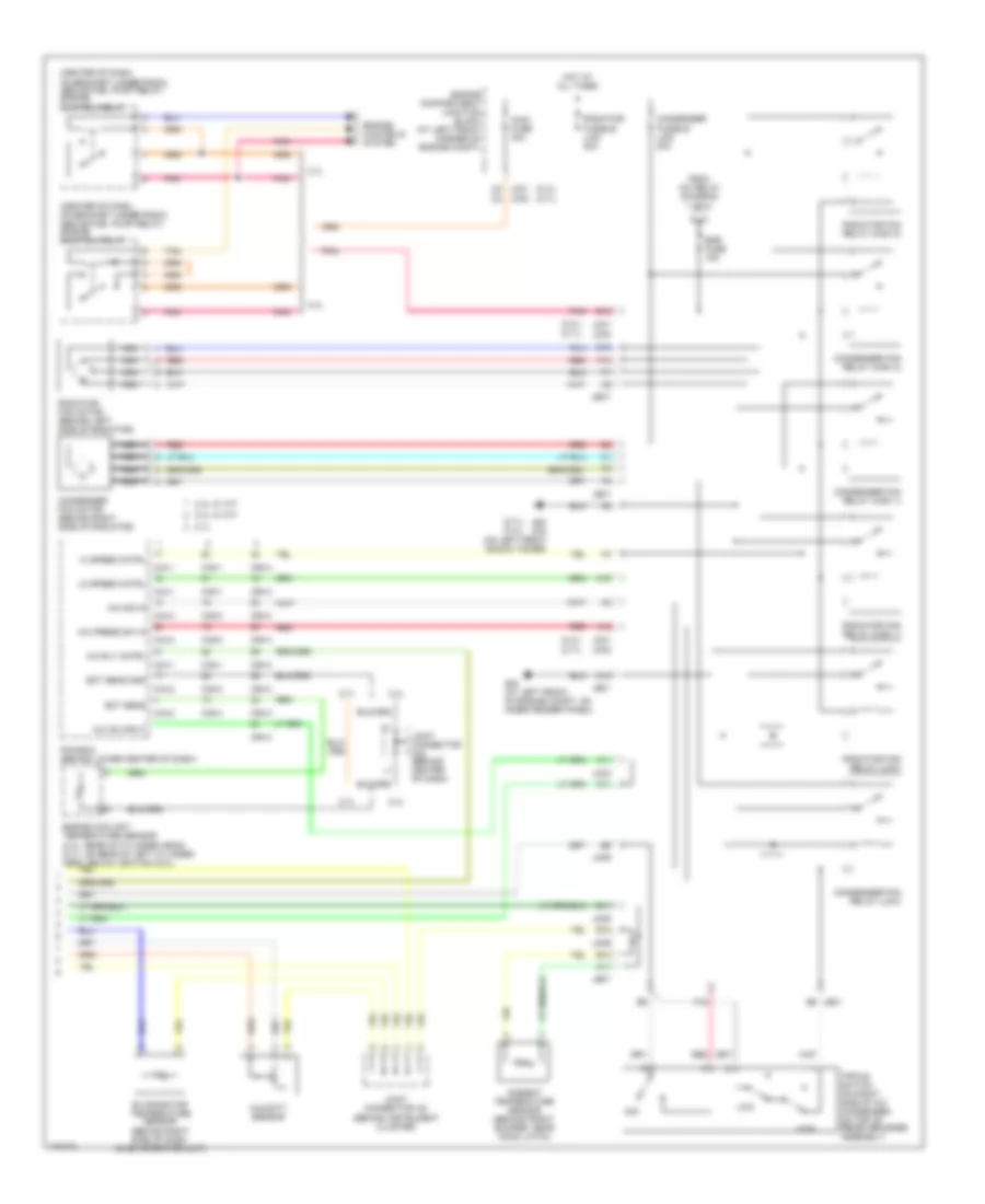
Automatic A/C Wiring Diagram (1 of 2) for Hyundai Sonata LX 2003

List of elements for Automatic A/C Wiring Diagram (1 of 2) for Hyundai Sonata LX 2003:
- (2.4l)
- (2.7l)
- (behind right side of dash) blower relay
- (under center of dash, behind ignition switch) g04
- A/c compressor
- A/c compressor fuse 10a
- A/c control module (behind center of dash)
- A/c on output
- A/c output
- A/c relay
- A10
- Amb temp sensor
- Aqs sensor
- B/l
- Blend door actuator (behind center of dash, on left end of hvac housing)
- Blnd dr actuator
- Blower fuse 30a
- Blower motor (behind right side of dash, on bottom of hvac housing)
- Blr feed back
- D12 jm09
- Def
- Defogger sw
- Defogger system
- Engine compartment junction block (at left front corner of engine compartment)
- Engine compartment junction block (at left front corner of engine compt)
- Etacm
- Evap sensor in
- F11 je01
- Floor
- Fre
- Fuse 10a
- Fuse 20a
- G01 (at right front of engine compt, on inner fender panel)
- G05 (under dash, on right lower ``a" pillar)
- Ground
- Hi speed cntrl
- High blower relay (behind right side of dash, below blower assembly)
- Hot at all times
- Hot in on
- Humidity sensor
- I/p-a
- I/p-g
- I/p-l
- I/p-m
- I17-1
- I17-2
- Ill+
- Ill-
- In-car sens in
- In-car sens out
- Intake actuator (behind right side of dash, on right end of hvac housing)
- Interior lights system
- Jc01 b12
- Jc02 b12
- Je01 b6
- Jm09 e7
- Joint connector i20 (behind instrument cluster)
- Joint connector mo8
- M33-3
- Memory power
- Mix
- Nca
- On input
- Passenger compartment junction block (behind left side of dash)
- Photo sens +
- Photo sensor (on top center of dash)
- Pnk
- Power transistor
- Power transistor (behind right side of dash, on right end of hvac housing)
- Rec
- Red
- Sensor +
- Sensor ground
- Temp act ccw
- Temp actuator
- Temp feed back
- Temperature actuator (behind right side of dash, on evaporator unit)
- To egr fuse (diagram 2 of 2)
- Vent
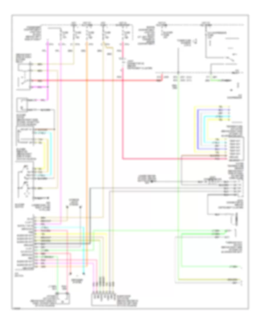
Automatic A/C Wiring Diagram (2 of 2) for Hyundai Sonata LX 2003
List of elements for Automatic A/C Wiring Diagram (2 of 2) for Hyundai Sonata LX 2003:
- (2.4l)
- (2.7l)
- (2.7l) (2.4l)
- (behind instrument cluster)
- (center of dash, on bracket under radio, above fuel pump relay) engine control relay
- 2.4l
- 2.4l w/ a/t
- 2.4l w/ m/t
- 2.7l
- A/c on input
- A/c press sw in
- A/c rly cntrl
- A/c sig in
- A10
- A11
- A12
- Ambient temperature sensor (behind front bumper, near hood latch)
- B10
- B12
- C10
- C11
- C44-1
- C44-2
- C44-3
- C45-1
- C45-2
- C45-4
- C94-3
- C94-4
- Condenser fan motor (behind right side of radiator)
- Condenser fan relay (high 1)
- Condenser fan relay (high 2)
- Condenser fan relay (low)
- Condenser fusible link 20a
- D11
- E10
- E12
- Ect sens
- Ect sens gnd
- Egr fuse 15a
- Engine compartment junction block (at left front corner of engine compt)
- Engine controls system
- Engine coolant temperature sensor (2.4l: rear of cylinder head) (2.7l: on rear of left cylinder head, below ignition coil)
- Evaporator temperature sensor (behind right side of dash, on evaporator unit)
- F10
- F12
- From a/c relay (diagram 1 of 2)
- G02 (at left front of engine compt, on inner fender panel)
- G20 g15 (on left front shock tower)
- Hi speed cntrl
- High
- Hot at all times
- Humidity sensor
- Jc01
- Jc01 c2
- Jc02
- Jc02 c2
- Je01
- Je01 e6
- Jeo1
- Jm09
- Joint connector c42 (behind center of dash)
- Joint connector i22
- Lo speed cntrl
- Low
- Main fuse 30a
- Mid
- Nca
- Pcm/ecm (behind lower center of dash)
- Pnk
- Radiator fan motor (behind left side of radiator)
- Radiator fan relay (high 1)
- Radiator fan relay (high 2)
- Radiator fan relay (low)
- Radiator fusible link 30a
- Red
- Tan
- Triple switch (on right side of a/c condenser, on top of receiver-drier assembly)
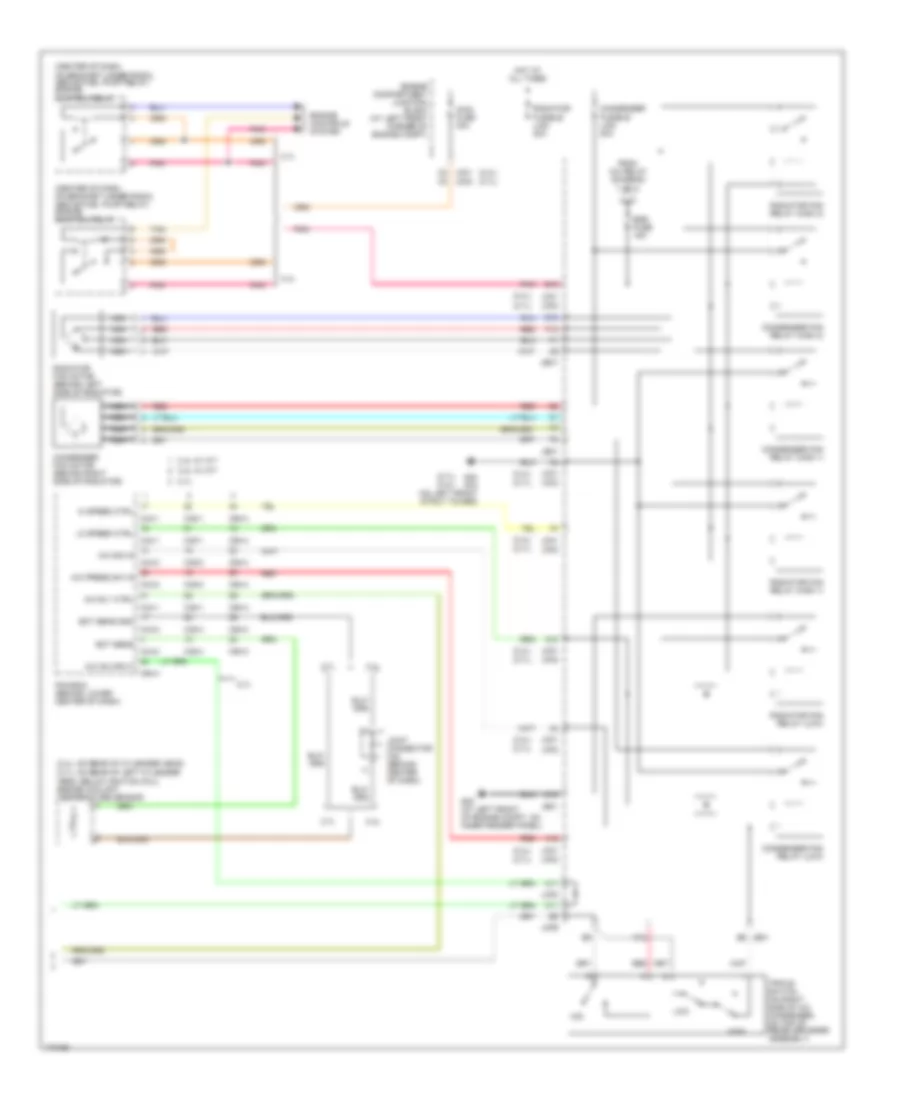
Manual A/C Wiring Diagram (1 of 2) for Hyundai Sonata LX 2003
List of elements for Manual A/C Wiring Diagram (1 of 2) for Hyundai Sonata LX 2003:
- (2.4l)
- (2.7l)
- (behind right side of dash) blower relay
- (under center of dash, behind ignition switch) g04
- A/c compressor
- A/c compressor fuse 10a
- A/c on out
- A/c relay
- A/c switch
- B/l
- Blend door actuator (behind center of dash,on left end of hvac housing)
- Blend dr act
- Blower fuse 30a
- Blower motor (behind right side of dash, on bottom of hvac housing)
- Blower resistor (behind right side of dash, on hvac housing)
- Blower switch
- Blr rly on in
- D12 jm09
- Def
- Defog sw
- Defogger system
- Engine compartment junction block (at left front corner of engine compartment)
- F11 je01
- Floor
- Fre
- Fuse 10a
- G05 (under dash, on right lower ``a" pillar)
- Gnd
- Ground
- Hot at all times
- Hot in on
- Hot in on or start
- I/p-a
- I/p-g
- I/p-l
- I/p-m
- Iii
- Iiii
- Illum +
- Illum -
- Intake actuator (behind right side of dash, on right end of hvac housing)
- Interior lights system
- Jc01 b12
- Jc02 b12
- Joint connector i20 (behind instrument cluster)
- Joint connector i22 (behind instrument cluster)
- Joint connector m08
- Mem pwr
- Mix
- Nca
- Off
- On in
- On input
- Passenger compartment junction block (behind left side of dash)
- Pnk
- Rec
- Red
- Tan
- Temp act
- Temperature actuator (behind right side of dash, on evaporator unit)
- Thermistor
- Thermostatic switch (behind right side of dash, on evaporator unit)
- To egr fuse (diagram 2 of 2)
- Vent
- Water temperature sensor (behind right side of dash, on heater core cover)
Manual A/C Wiring Diagram (2 of 2) for Hyundai Sonata LX 2003
List of elements for Manual A/C Wiring Diagram (2 of 2) for Hyundai Sonata LX 2003:
- (2.4l)
- (2.4l) (2.7l)
- (2.4l: on rear of cylender head)
- (2.7l)
- (2.7l) (2.4l)
- (2.7l: on rear of left cylender
- (center of dash, on bracket under radio, above fuel pump relay) engine control relay
- 2.4l
- 2.4l w/ a/t
- 2.4l w/ m/t
- 2.7l
- A/c on input
- A/c press sw in
- A/c rly ctrl
- A/c sig in
- A10
- A11
- A12
- B10
- C10
- C11
- C44-1
- C44-2
- C44-3
- C45-1
- C45-2
- C45-4
- C94-3
- C94-4
- Condenser fan motor (behind right side of radiator)
- Condenser fan relay (high 1)
- Condenser fan relay (high 2)
- Condenser fan relay (low)
- Condenser fusible link 20a
- E10
- Ect sens
- Ect sens gnd
- Egr fuse 15a
- Engine compartment junction block (at left front corner of engine compt)
- Engine controls system
- F10
- F12
- From a/c relay (diagram 1 of 2)
- G02 (at left front of engine compt, on inner fender panel)
- G20 g15 (on left front strut tower)
- Head, below ignition coil) engine coolant temperature sensor
- Hi speed ctrl
- High
- Hot at all times
- Jc01
- Jc01 c2 c2
- Jc01 jc02
- Jc02
- Je01
- Je01 e6
- Jeo1
- Jm09
- Joint connector c42 (behind center of dash)
- Lo speed ctrl
- Low
- Main fuse 30a
- Mid
- Nca
- Pcm/ecm (behind lower center of dash)
- Pnk
- Radiator fan motor (behind left side of radiator)
- Radiator fan relay (high 1)
- Radiator fan relay (high 2)
- Radiator fan relay (low)
- Radiator fusible link 30a
- Red
- Tan
- Triple switch (on right side of a/c condenser, on top of receiver-drier assembly)