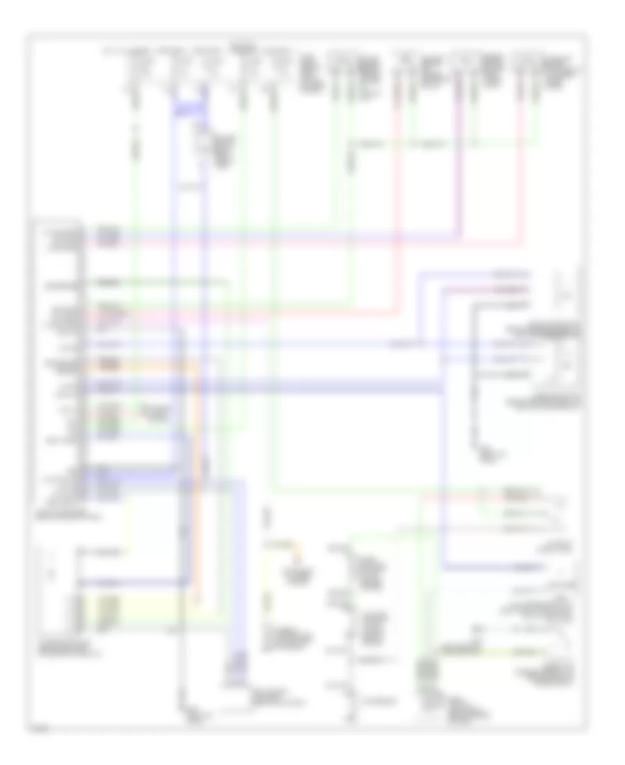
AIR CONDITIONING
Automatic A/C Wiring Diagram for Infiniti QX4 2000
List of elements for Automatic A/C Wiring Diagram for Infiniti QX4 2000:
- (left front of engine compt)
- 14u
- 16w
- 20% fre fre 20% fre fre
- A/c auto amplifier (behind center of dash)
- A/c relay (in relay box)
- Acrly
- Air mix door motor (behind center of dash, on bottom of heater unit)
- Amb sens
- Ambient air temperature switch (center front of engine compt)
- Ambient sensor (center front of eng compt)
- Arcon
- Bat
- Blower motor (below right side of dash)
- Blwr motor
- Cel/fht
- Comp on
- Compressor
- Diode (iacv-ficd solenoid valve) (center of dash)
- Dual pressure switch (right front of eng compt, on a/c liquid tank)
- Eccs control module (ecm) (behind center of dash)
- Fan control amplifier (behind glove box)
- Fan f/b
- Fan gate
- Fre rec fre rec
- Fre(+) rec(-)
- Fuse 15a
- Fuse 7.5a
- Fuse block (behind dash, left of steering column)
- G100
- G200 (left kick panel)
- Grd
- Grd sens
- High
- Hot at all times
- Hot in on
- Hot in on or start
- Iacv-ficd solenoid valve (on left rear of engine)
- Ign
- Ill -
- In-vehicle sensor (attached to instrument lower cover)
- Incar sens
- Instrument cluster system
- Intake door motor (behind glove box, on heater intake unit)
- Intake sens
- Intake sensor (behind center of dash, on cooling unit)
- Interior lights system
- Lan-sig
- Light +
- Low
- Mode door motor (behind center of dash, on bottom of heater unit)
- Norm
- Rec(+) fre(-)
- Sun sens
- Sunload sensor (on center defroster grille)
- Tasw
- Thermal transmitter (on top front of engine)
- Vactr
- Water sens
 English