ANTI-LOCK BRAKES
Anti-lock Brakes Wiring Diagram for Hyundai Accent GL 2004
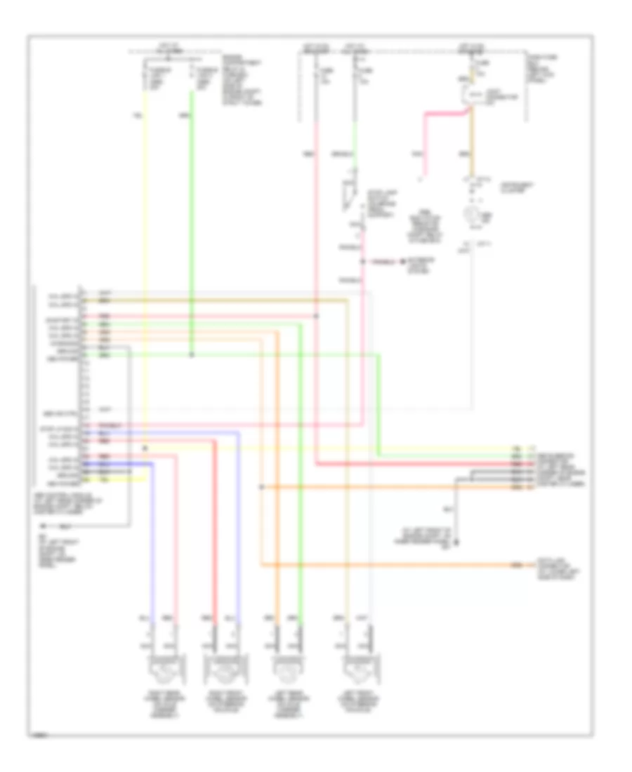
List of elements for Anti-lock Brakes Wiring Diagram for Hyundai Accent GL 2004:
- (at left front of engine compt, on inner fender panel) g01
- Abs bleeding
- Abs control module (at left rear corner of engine compt, below master cylinder)
- Abs ind
- Abs ind ctrl
- Connector (at left rear corner of engine compt, near
- Dash fuse box (behind left kick panel)
- Data link connector (at lower left side of dash)
- Diagnosis
- Engine compartment relay & fuse box (on left side of engine compt, in front of strut tower)
- Exterior lights system
- Fuse 10a
- Fusible link 1 (abs) 30a
- Fusible link 2 (abs) 30a
- G01 (at left front of engine compt, on inner fender panel)
- Ground
- Hot at all times
- Hot in on or start
- Instrument cluster
- Joint connector m31
- Left front wheel sensor (on steering knuckle)
- Left rear wheel sensor (on axle carrier assembly)
- M71-1
- M71-2
- Master cylinder)
- Mem power
- Nca
- On/start in
- Pnk
- Pre- excitation resistor (in engine compt relay & fuse box)
- Red
- Right front wheel sensor (on steering knuckle)
- Right rear wheel sensor (on axle carrier assembly)
- Stop lamp switch (on brake pedal support)
- Stop lp sig in
- Whl spd in
 English