ANTI-LOCK BRAKES
Anti-lock Brake Wiring Diagrams for Hyundai Accent L 1998
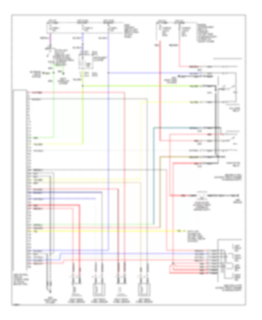
List of elements for Anti-lock Brake Wiring Diagrams for Hyundai Accent L 1998:
- (dlx) (std)
- Abs control module (in right side of trunk, behind trim)
- Abs ground
- Abs ind
- Abs modulator (in right front corner of engine compt)
- Abs relay box (on right front corner of engine compt)
- Dash fuse box (below left side of dash, at kick panel)
- Data link connector (on left side of dash, above coin box)
- E05
- Engine compartment relay & fuse box (on left side of engine compt, in front of shock tower)
- Exterior lights system
- Fail safe relay
- Fuse 10 10a
- Fuse 2 10a
- Fuse 4 15a
- Fusible link g 30a (pnk)
- G201 (right side of dash)
- Hot at all times
- Hot in on or start
- I07-2
- I08-1
- I08-2
- Instrument cluster
- Left front sol
- Left front wheel sensor
- Left rear sol
- Left rear wheel sensor
- M79
- Nca
- Pump motor (on right front corner of engine compt)
- Pump motor relay
- Red
- Right front sol
- Right front wheel sensor
- Right rear sol
- Right rear wheel sensor
- Shift interlock system
- Stoplight switch (behind left side of dash, on brake pedal support bracket)
 English