ANTI-LOCK BRAKES
Anti-lock Brakes Wiring Diagram for Hyundai Accent SE 2009
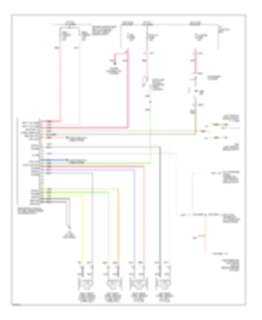
List of elements for Anti-lock Brakes Wiring Diagram for Hyundai Accent SE 2009:
- (left rear of engine compt) pcm
- A/t
- Abs 1 fusible link 40a
- Abs 2 fusible link 40a
- Abs control module (at right rear corner of engine compt)
- Abs fuse 10a
- Abs ind
- Abs ind ctrl
- Batt voltage
- C01-1
- Can high
- Can low
- Cluster fuse 10a
- Computer data lines system
- Data link connector (at lower left side of dash)
- Ecm (left rear of engine compt)
- Engine compartment relay & fuse box (on left side of engine compt)
- G12 (at left kick panel)
- Ground
- Hot at all times
- Hot in on or start
- I/p junction box
- I/p-f
- I/p-g
- Instrument cluster
- K-line
- Left front wheel sensor (in left front wheelwell)
- Left rear wheel sensor (at left "c" pillar)
- M/t
- M09-1
- M09-3
- Multipurpose check connector (left rear of engine compt)
- Nca
- On/start in
- Pnk
- Power
- Power distribution system
- Red
- Right front wheel sensor (in right front wheelwell)
- Right rear wheel sensor (at right "c" pillar)
- Signal
- Stop lamp sw
- Stop lamp switch (on brake pedal support)
- Stop lp fuse 15a
- Tire pressure monitoring module (behind center of dash)
- Usa
- Wheel sens sig
 English