ANTI-LOCK BRAKES
Anti-lock Brake Wiring Diagrams for Hyundai Elantra 1996
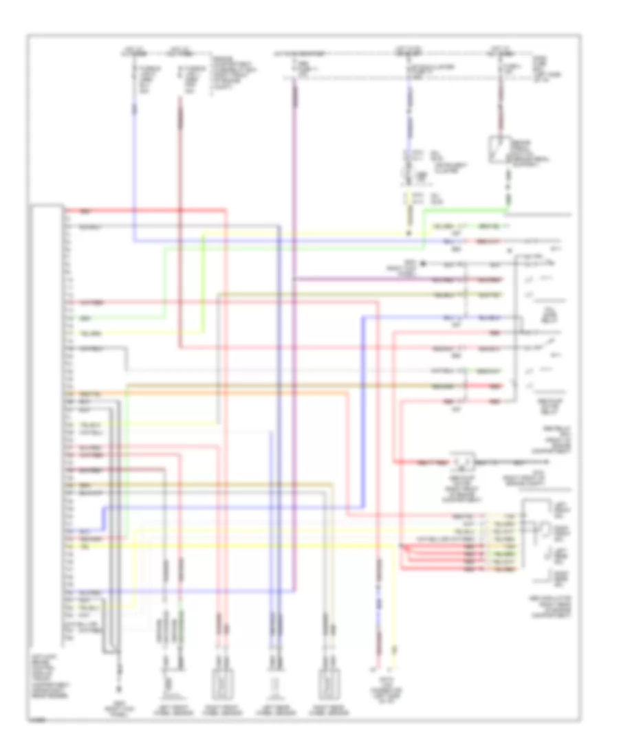
List of elements for Anti-lock Brake Wiring Diagrams for Hyundai Elantra 1996:
- (gl) (gls)
- Abs fuse 11 10a
- Abs ind
- Abs modulator (right rear of engine compartment)
- Abs pump motor (right front of engine compartment)
- Abs pump motor relay
- Abs relay box (front of engine compartment)
- Antilock brake control module (trunk compartment, inside right rear fender)
- Brake pedal switch (brake pedal support)
- Dash fuse box (left side of i/p)
- Data link connector (left side of i/p)
- E58
- Engine compartment fuse/relay box (right front of engine compt)
- Etacs,cluster fuse 10 10a
- Fail safe relay
- Fuse 4 15a
- Fusible link j (abs) pnk 30a
- G101 (right front of engine compt)
- G203 (right kick panel)
- Hot at all times
- Hot in on or start
- I01-1
- I01-3
- I04-3
- Instrument cluster
- Left front sol
- Left front wheel sensor
- Left rear sol
- Left rear wheel sensor
- M87
- Red
- Right front sol
- Right front wheel sensor
- Right rear sol
- Right rear wheel sensor
- Tan
 English