ANTI-LOCK BRAKES
Anti-lock Brake Wiring Diagrams for Hyundai Elantra GLS 2001
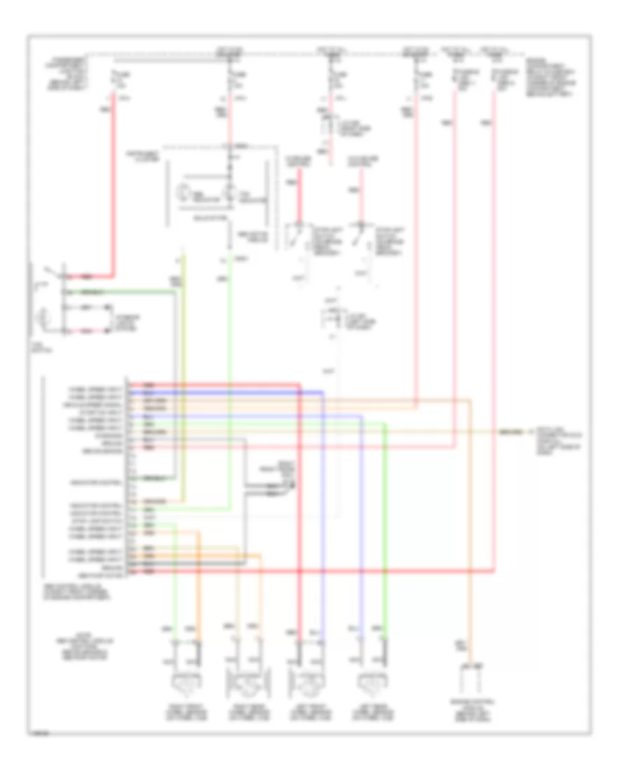
List of elements for Anti-lock Brake Wiring Diagrams for Hyundai Elantra GLS 2001:
- (right front frame rail) g118
- Abs active module
- Abs control module (in right front corner of engine compartment)
- Abs indicator
- Abs pump motor
- Abs solenoids
- C83
- Connector (dlc) (partial) (on left side of dash)
- Data link
- Diagnosis
- Engine compartment relay & fuse box (in right front corner of engine compartment, behind battery)
- Engine control module (behind left side of dash)
- Fuse 10a
- Fuse 15a
- Fusible link (abs 1) 30a
- Fusible link (abs 2) 30a
- Ground
- Hot at all times
- Hot in on or start
- I/p-b
- I/p-h
- I/p-j
- Indicator control
- Instrument cluster
- Interior lights system
- J/c c91 (left side of dash)
- J/c m36 (right side of dash)
- Left front wheel sensor (on wheel hub)
- Left rear wheel sensor (on wheel hub)
- M09-3
- Nca
- Note: abs control module contains: abs solenoids & abs pump motor
- Passenger compartment junction block (behind left side of dash)
- Pnk
- Red
- Right front wheel sensor (on wheel hub)
- Right rear wheel sensor (on wheel hub)
- Solid state
- Start/on input
- Stop lamp switch
- Stoplight switch (on brake pedal bracket)
- Tcs indicator
- Tcs switch
- Vehicle speed signal
- W/cruise control
- W/o cruise control
- Wheel speed input
 English