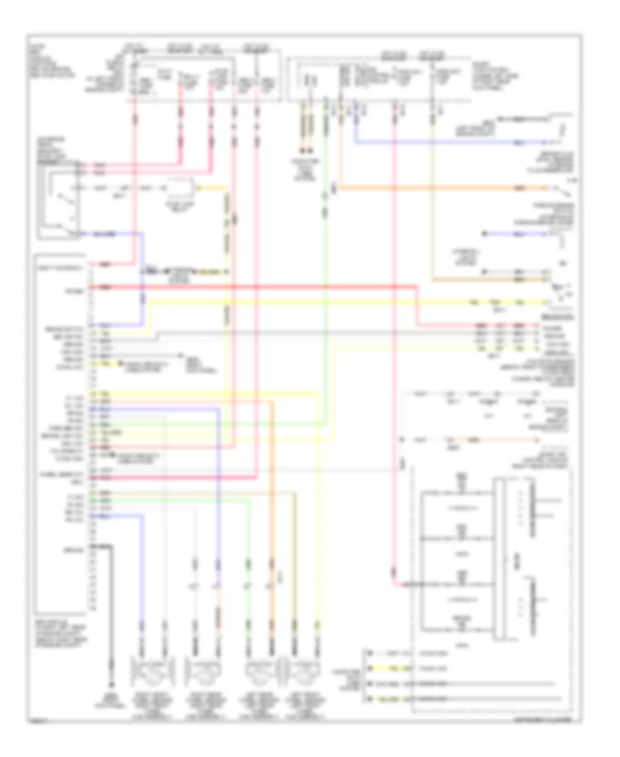
ANTI-LOCK BRAKES
Anti-lock Brakes Wiring Diagram for Hyundai Elantra Limited 2012
List of elements for Anti-lock Brakes Wiring Diagram for Hyundai Elantra Limited 2012:
- (on brake pedal bracket) stop lamp switch
- (sedan: right rear of engine compt)
- +ecu
- A/t
- Abs 1 fuse 40a
- Abs 2 fuse 30a
- Abs 3 fuse 10a
- Abs ind
- B-can high
- B-can low
- B-can transceiver
- Brake fluid level sensor (in brake fluid reservoir)
- Brake ind
- Brake light sw
- Brake switch
- Brk flu
- C-can high
- C-can low
- C-can transceiver
- Can high
- Can low
- Cng-ab
- Cng-mk
- Computer data lines system
- E/r fuse & relay box (in left front corner of engine compt)
- Ec11
- Ecm/pcm (left rear of engine compt)
- Ecu 3 fuse 10a
- Ef11
- Em11
- Em61
- Esc ind
- Esc module (wagon: left rear of engine compt)
- Esc off ind
- Esc off sw
- Esc switch
- Exterior lights system
- Fl sig
- Fl vcc
- Fr sig
- Fr vcc
- Ge02 (left front of engine compt)
- Ge06 (right kick panel)
- Ground
- High
- Hot at all times
- Hot in on or start
- I/p-c
- I/p-e
- I/p-f
- I/p-g
- I/p-h
- Instrument cluster
- Interior lights system
- Ips control module
- Le sen
- Left front wheel sensor (left front wheel hub assembly)
- Left rear wheel sensor (left rear wheel hub assembly)
- Low
- M/t
- Micom
- Module 2 fuse 7.5a
- Module 3 fuse 7.5a
- Multi fuse
- Nca
- Note: esc module contains: esc solenoids, esc pump motor
- Off
- Park brk sw
- Parking brake switch (on brake of parking brake lever)
- Parking brk sw
- Pnk
- Power
- Red
- Right front wheel sensor (right front wheel hub assembly)
- Right rear wheel sensor (right rear wheel hub assembly)
- Rl sig
- Rl vcc
- Rr sig
- Rr vcc
- Smart junction box (under left side of dash, near kick panel)
- Smart key control module (right rear of dash)
- Stop lamp fuse 15a
- Stop lamp relay
- Valve relay
- Vbatt motor rly
- Wheel sens out
- Yaw rate sensor (sedan: front passenger's floor area) (wagon: below center console)
 English