ANTI-LOCK BRAKES
Anti-lock Brakes Wiring Diagram (1 of 2) for Hyundai Santa Fe SE 2009

List of elements for Anti-lock Brakes Wiring Diagram (1 of 2) for Hyundai Santa Fe SE 2009:
- (2.7l)
- (2.7l) (3.3l)
- (2.7l, euro 4)
- (3.3l)
- (behind lower left end of dash)
- (behind right side of dash) g37 g53
- +ecu
- 2.7l
- 3.3l
- Abs ind ctrl
- Brake light switch
- C123
- C130-a
- C23
- C30-a
- Can high
- Computer data lines system
- Data link connector
- Diagnosis
- Ebd ind ctrl
- Esc 1 fusible link 40a
- Esc 2 fusible link 20a
- Esc control module (left rear of engine compt, below brake master cylinder)
- Esc fuse 10a
- Esc ind ctrl
- Esc off ind ctrl
- Esc passive
- Ground
- Hot at all times
- Hot in on or start
- I/p junction block (behind lower left end of dash)
- I/p-j
- J/c c23 (2.7l) (top left side of engine) j/c c123 (3.3l) (below right end of dash)
- Left front wheel sensor (top of wheelwell)
- Left rear wheel sensor (above wheelwell)
- Low can
- Multipurpose check connector (left rear of engine compt)
- Nca
- Note: esc control module contains: esc solenoids, esc pump motor
- Parking brake sw
- Pcm (left rear of engine compt)
- Red
- Right front wheel sensor (top of wheelwell)
- Right rear wheel sensor (above wheelwell)
- Stop lamp switch (above brake pedal, on bracket)
- Stop lp fuse 15a
- Tpms module (behind center of dash)
- U/h junction box (left rear of engine compt)
- Vbatt motor rly
- Vlv block rly
- Wheel spd sens
- Wheel spd sens out
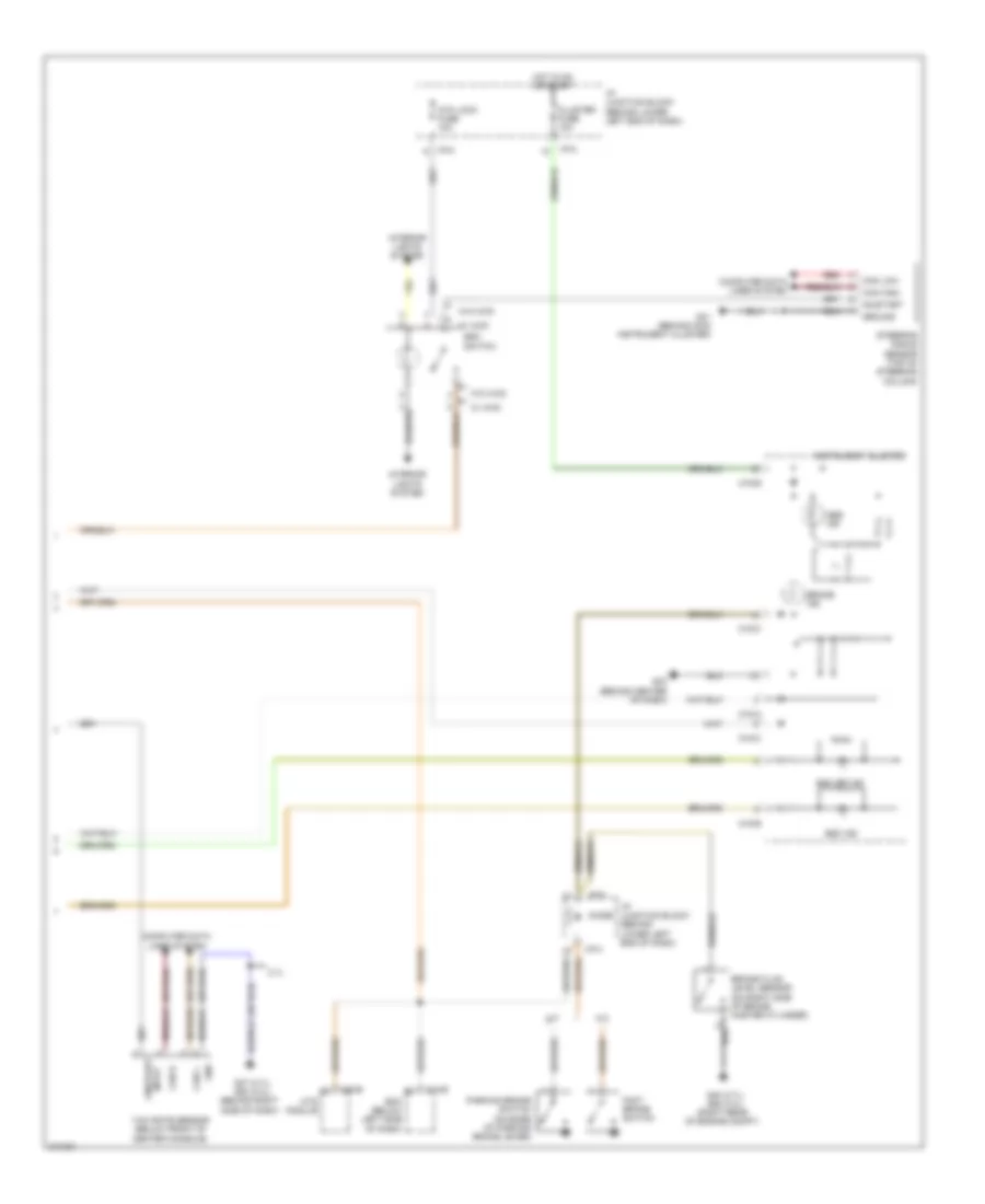
Anti-lock Brakes Wiring Diagram (2 of 2) for Hyundai Santa Fe SE 2009
List of elements for Anti-lock Brakes Wiring Diagram (2 of 2) for Hyundai Santa Fe SE 2009:
- (2.7l) g37 (3.3l) g53 (behind right side of dash)
- (2.7l) g40 (3.3l) g55 (right rear of engine compt)
- (or red)
- 2.7l
- A/t
- Abs ind
- Atm lock fuse 10a
- Bcm (below left side of dash)
- Brake fluid level sensor (on right side of brake master cylinder)
- Brake ind
- Can h
- Can high
- Can l
- Can low
- Cluster fuse 10a
- Computer data lines system
- Diode
- Esc ind
- Esc off ind
- Esc switch
- Foot brake switch
- G31 (behind main instrument cluster)
- G33 (behind center of dash)
- Gnd
- Ground
- Hot in on or start
- I/p junction block (behind lower left end of dash)
- I/p-h
- I/p-k
- I/p-m
- Input on/start
- Instrument cluster
- Interior lights system
- M/t
- M13-b
- M15-a
- M15-b
- M15-c
- M48-b
- Mts module
- On/start
- Parking brake switch (on base of parking brake lever)
- Red
- Steering angle sensor (top of steering column)
- W/ 4wd
- W/o 4wd
- Yaw rate sensor (below front of center console)