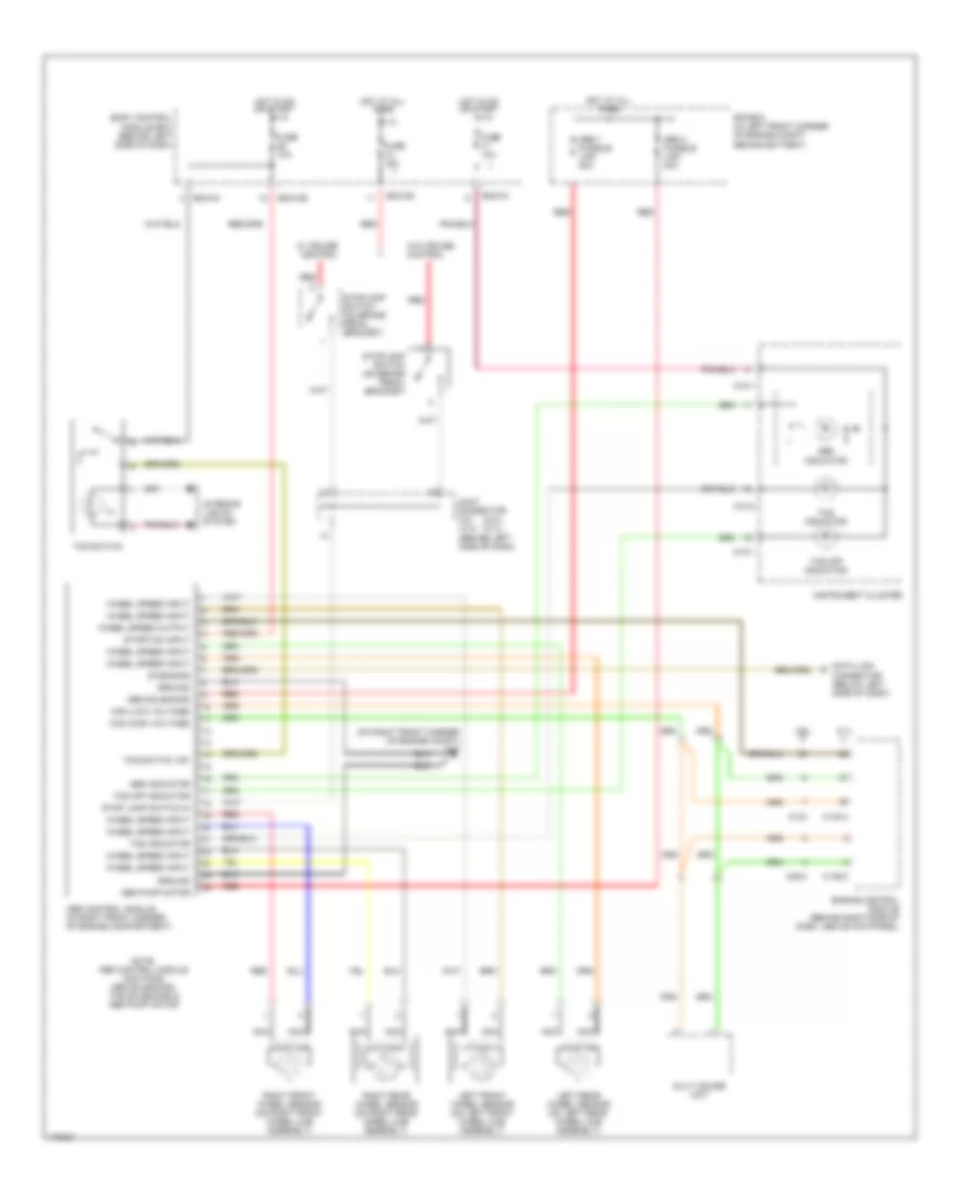
ANTI-LOCK BRAKES
Anti-lock Brakes Wiring Diagram for Hyundai Tiburon 2003
List of elements for Anti-lock Brakes Wiring Diagram for Hyundai Tiburon 2003:
- (2.0l) (2.7l)
- (on right front corner of engine compt) g17
- 2.0l
- 2.7l
- Abs 1 fusible link 30a
- Abs 2 fusible link 30a
- Abs control module (in right front corner of engine compartment)
- Abs indicator
- Abs pump motor
- Abs solenoids
- Bcm-ce
- Bcm-im
- Bcm-km
- Body control module box (behind left side of dash)
- C133
- C133-4
- C136-3
- C36-3
- Can (high voltage)
- Can (low voltage)
- Connector (below left side of dash)
- Data link
- Diagnosis
- E/r box (in left front corner of engine compt, behind battery)
- Engine control module (behind right side of dash, above kick panel)
- Fuse 10a
- Fuse 15a
- Ground
- Hot at all times
- Hot in on or start
- Ill
- Instrument cluster
- Interior lights system
- Joint connector c41 c141 (behind left side of dash)
- Left front wheel sensor (on left front wheel hub assembly)
- Left rear wheel sensor (on left rear wheel hub assembly)
- M10-1
- M10-2
- Multi gauge unit
- Nca
- Note: abs control module contains: abs solenoids, tcs solenoids & abs pump motor
- Red
- Right front wheel sensor (on right front wheel hub assembly)
- Right rear wheel sensor (on right rear wheel hub assembly)
- Start/on input
- Stop lamp switch in
- Stoplamp switch (on brake pedal bracket)
- Tcs indicator
- Tcs off indicator
- Tcs switch
- Tcs switch "on"
- W/ cruise control
- W/o cruise control
- Wheel speed input
- Wheel speed output
 English