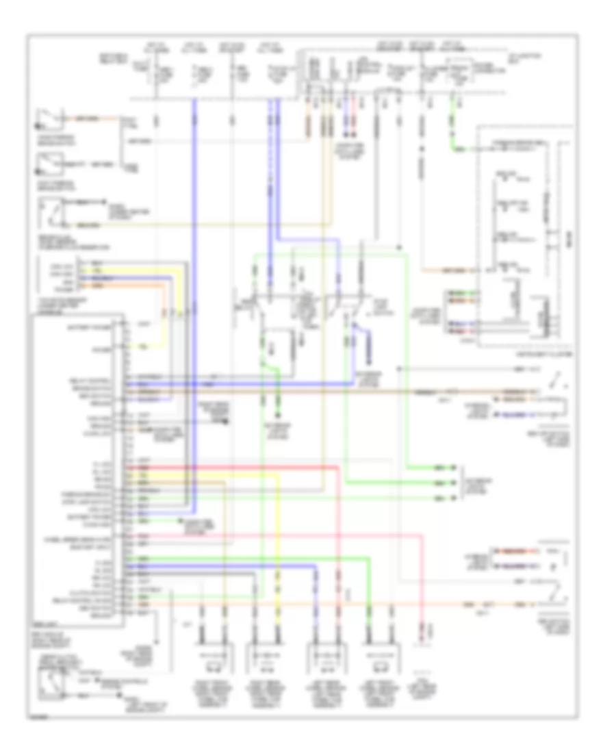
ANTI-LOCK BRAKES
Anti-lock Brakes Wiring Diagram for Hyundai Tucson GL 2012
List of elements for Anti-lock Brakes Wiring Diagram for Hyundai Tucson GL 2012:
- (left front of
- (near clutch
- (right rear of engine compt)
- Abs 1 fuse 40a
- Abs 2 fuse 40a
- Abs fuse 7.5a
- Abs ind
- Battery power
- Brake fluid level sensor (in brake fluid reservoir)
- Brake switch
- Brk fld
- C-can high
- C-can low
- Can hi
- Can high
- Can low
- Cf11
- Chg-k
- Cluster fuse 10a
- Clutch switch
- Computer data lines system
- Dbc ind
- Dbc relay
- Dbc switch
- Dbc switch (left side of dash)
- E/r fuse & relay box
- Engine compt)
- Engine controls system
- Esc ind
- Esc module (right rear of engine compt)
- Esc off ind
- Esc off switch (left side of dash)
- Esc switch
- Esc unit
- Exterior lights system
- Fl sig
- Fl vcc
- Foot parking brake switch
- Foot type
- Fr sig
- Fr vcc
- Ghg01
- Ghg03 (under center of dash)
- Ghg06
- Gnd
- Ground
- Hand parking brake switch
- Hand type
- Hot at all times
- Hot in on or start
- I/p junction box
- I/p-c
- I/p-d
- I/p-g
- I/p-h
- I/p-j
- Icm relay box (top left of dash)
- Instrument cluster
- Inter face
- Interior lights system
- Ips control module can lo
- Left front wheel sensor (left front wheel hub assembly)
- Left rear wheel sensor (left rear wheel hub assembly)
- Lvl
- M/t
- M04-a
- M15-a
- Mc11
- Mc21
- Micom
- Module 1 fuse 10a
- Multi fuse
- Nca
- On/start input
- Parking brake ind
- Parking brake sw
- Parking brk sw
- Pcm (left rear of engine compt)
- Pedal bracket)
- Pnk
- Power
- Power connector
- Red
- Relay control
- Relay control on sig
- Right front wheel sensor (right front wheel hub assembly)
- Right rear wheel sensor (right rear wheel hub assembly)
- Rl sig
- Rl vcc
- Room lp fuse 10a
- Rr sig
- Rr vcc
- Stop lamp switch
- Stop lp fuse 10a
- Transceiver b-can
- Transceiver c-can
- Wheel speed sens in (fr)
- Yaw rate sensor (under center console)
 English