ANTI-LOCK BRAKES
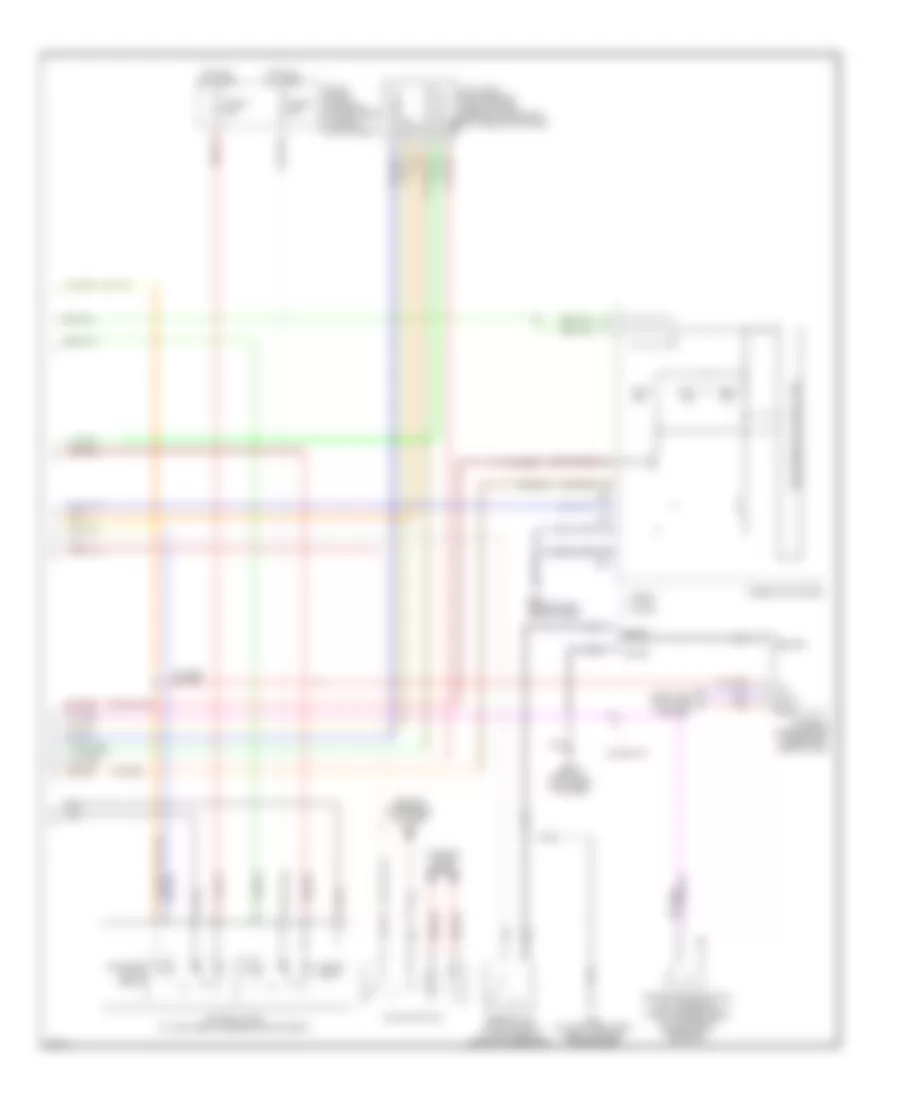
Anti-lock Brakes Wiring Diagram, Early Production (1 of 2) for Infiniti G35 2004

List of elements for Anti-lock Brakes Wiring Diagram, Early Production (1 of 2) for Infiniti G35 2004:
- (unused pins not shown)
- Abs w/l
- Bls
- Can-h
- Can-l
- Computer data line system
- Coupe
- Coupe (m/t)
- Data link connector (lower left side of dash)
- Diag-k
- Dp fl
- Dp fr
- Dp rl
- Dp rr
- Ds fl
- Ds fr
- Ds rl
- Ds rr
- E101
- E43 (on left front side of engine compartment)
- Fl hsv
- Fl mv-av
- Fl mv-ev
- Fl usv
- Fr hsv
- Fr mv-av
- Fr mv-ev
- Fr usv
- Fuse 14 10a
- Fuse 20 10a
- Fuse 82 10a
- Fuse block (j/b) (behind left kick panel)
- Gnd
- Gnd1
- Gnd2
- Hot at all times
- Hot in on or start
- Ipdm e/r (intelligent power distribution module engine room) (at right rear of engine compartment)
- Left front wheel sensor (on left front steering knuckle assembly)
- Left rear wheel sensor (on left rear wheel hub assembly)
- Lis
- Nca
- Pkb sw
- Pnk
- Pressure sensor
- Psm
- Pss
- Psu
- Red
- Right front wheel sensor (on right front steering knuckle assembly)
- Right rear wheel sensor (on right rear wheel hub assembly)
- Rl mv-av
- Rl mv-ev
- Rr mv-av
- Rr mv-ev
- Sedan
- Slip lamp
- Stop lamp switch (on brake pedal bracket)
- Vcc
- Vdc actuator (at left rear corner of engine compartment)
- Vdc off lamp
- Vdc off sw
- Vdc/tcs/abs control unit (behind left side of dash)
- Vout
- Yrsm
- Yrsref
- Yrss
- Yrst
- Yrsu
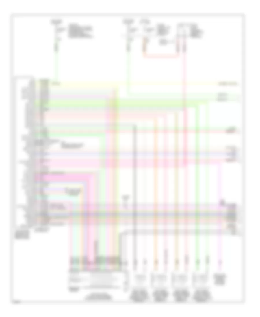
Anti-lock Brakes Wiring Diagram, Early Production (2 of 2) for Infiniti G35 2004
List of elements for Anti-lock Brakes Wiring Diagram, Early Production (2 of 2) for Infiniti G35 2004:
- (behind instrument cluster) m30
- 12v
- Abs ind
- Bite
- Brake fluid level switch (at left rear of engine compartment)
- Can-h
- Can-l
- Combination meter
- Computer data line system
- Coupe
- Coupe (m/t)
- E43 (on left front side side of engine compartment)
- Fuse & fusible link block (at right rear of engine compartment)
- Fuse j 50a
- Fuse k 30a
- Gnd
- Ground
- Hot at all times
- Ill
- Interior lights system
- M19
- M20
- M30 (behind instrument cluster)
- M66 (behind right side of dash)
- Motor relay
- Nca
- Output bs
- Output drs
- Parking brake switch (m/t: at base of parking brake lever) (a/t: on parking brake pedal bracket)
- Red
- Reference
- Sedan
- Slip ind
- Solenoid valve relay
- Steering angle sensor (under left side of dash)
- Unified meter control unit
- Vdc off
- Vdc off switch
- Vdc relay box (at left rear of engine compartment)
- Yaw rate/ side g sensor (under center console, forward of shift selector lever)
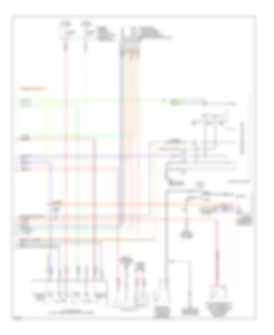
Anti-lock Brakes Wiring Diagram, Late Production (1 of 2) for Infiniti G35 2004
List of elements for Anti-lock Brakes Wiring Diagram, Late Production (1 of 2) for Infiniti G35 2004:
- (unused pins not shown)
- Abs w/l
- Bls
- Can-h
- Can-l
- Computer data line system
- Coupe
- Coupe (m/t)
- Data link connector (lower left side of dash)
- Diag-k
- Dp fl
- Dp fr
- Dp rl
- Dp rr
- Ds fl
- Ds fr
- Ds rl
- Ds rr
- E101
- E43 (on left front side of engine compt)
- Fl hsv
- Fl mv-av
- Fl mv-ev
- Fl usv
- Fr hsv
- Fr mv-av
- Fr mv-ev
- Fr usv
- Fuse 14 10a
- Fuse 20 10a
- Fuse 82 10a
- Fuse block (j/b) (behind left kick panel)
- Gnd
- Gnd1
- Gnd2
- Hot at all times
- Hot in on or start
- Ipdm e/r (intelligent power distribution module engine room) (at right rear of engine compartment)
- Left front wheel sensor (on left front steering knuckle assembly)
- Left rear wheel sensor (on left rear wheel hub assembly)
- Lis
- Nca
- Pkb sw
- Pnk
- Pressure sensor
- Psm
- Pss
- Psu
- Red
- Right front wheel sensor (on right front steering knuckle assembly)
- Right rear wheel sensor (on right rear wheel hub assembly)
- Rl mv-av
- Rl mv-ev
- Rr mv-av
- Rr mv-ev
- Sedan
- Slip lamp
- Stop lamp switch (on brake pedal bracket)
- Vcc
- Vdc actuator (at left rear corner of engine compartment)
- Vdc off lamp
- Vdc off sw
- Vdc/tcs/abs control unit (behind left side of dash)
- Vout
- Yrsm
- Yrsref
- Yrss
- Yrst
- Yrsu
Anti-lock Brakes Wiring Diagram, Late Production (2 of 2) for Infiniti G35 2004
List of elements for Anti-lock Brakes Wiring Diagram, Late Production (2 of 2) for Infiniti G35 2004:
- (behind instrument cluster) m30
- 12v
- Abs ind
- Bite
- Brake fluid level switch (at left rear of engine compartment)
- Can-h
- Can-l
- Combination meter
- Computer data line system
- Coupe
- Coupe (m/t)
- E43 (on left front side of engine compartment)
- Fuse & fusible link block (at right rear of engine compartment)
- Fuse j 50a
- Fuse k 30a
- Gnd
- Ground
- Hot at all times
- Ill
- Interior lights system
- M19
- M20
- M30 (behind instrument cluster)
- M66 (behind right side of dash)
- Motor relay
- Nca
- Output bs
- Output drs
- Parking brake switch (m/t: at base of parking brake lever) (a/t: on parking brake pedal bracket)
- Red
- Reference
- Sedan
- Slip ind
- Solenoid valve relay
- Steering angle sensor (under left side of dash)
- Unified meter control unit
- Vdc off
- Vdc off switch
- Vdc relay box (at left rear of engine compartment)
- Yaw rate/ side g sensor (under center console, forward of shift selector lever)