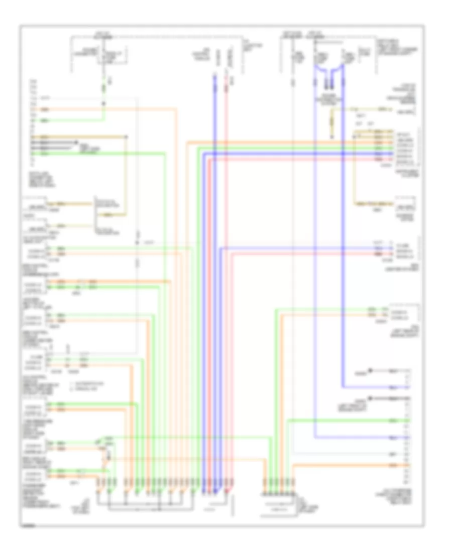
COMPUTER DATA LINES
Computer Data Lines Wiring Diagram for Hyundai Tucson Limited 2013
List of elements for Computer Data Lines Wiring Diagram for Hyundai Tucson Limited 2013:
- (steering column)
- (top of transaxle) (m/t) vehicle speed sensor
- 4p out
- 4wd ecm (bottom of left "a" pillar)
- A/c control module (behind center of dash, forward of shift lever)
- A/t
- A/v & navigation head unit
- Abs 1 fuse 40a
- Abs 2 fuse 40a
- Abs fuse 7.5a
- Audio
- Automatic a/c
- B-can hi
- B-can lo
- Bcm (center of dash)
- C-can hi
- C-can lo
- Chg-k
- Data link connector (below left side of dash)
- E/r fuse & relay box (left front corner of engine compt)
- Eps control module
- Esc module (right rear of engine compt)
- Ghg01 (left front of engine compt)
- Ghg02
- Gm01 (left side of dash)
- Hot at all times
- Hot in on or start
- I/p junction box
- I/p-h
- I/p-j
- Instrument cluster
- Ips control module
- J/c jc01 (left side of dash)
- J/c jm01 (top left of dash)
- K-line
- M/t
- M02-a
- M13-b
- M15-a
- M17-b
- M41-b
- M43-b
- M45-b
- M50-a
- Manual a/c
- Mc11
- Mc21
- Mf11
- Mf21
- Mr01
- Multi fuse
- Multipurpose check connector (in e/r fuse & relay box)
- Passenger occupant detection sensor (under front passenger's seat)
- Pcm (left rear of engine compt)
- Power connector
- Power distribution system
- Red
- Room lp fuse 10a
- Srs control module (under center of dash)
- Sunroof motor
- Tire pressure monitoring module (right side of dash)
- Veh spd
- W/ a/v & navigation
- W/o a/v & navigation
 English