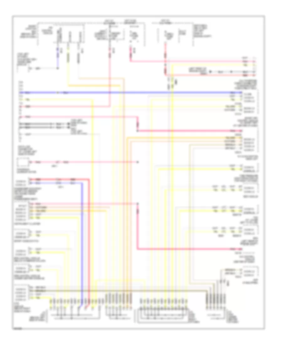
COMPUTER DATA LINES
Computer Data Lines Wiring Diagram for Hyundai Veloster 2012
List of elements for Computer Data Lines Wiring Diagram for Hyundai Veloster 2012:
- (left front of engine compt)
- (top left of dash) (w/o smart key) immobilizer module
- (top left side of dash) gm02
- (under passenger's seat)
- 4p out
- A/c control module (center of dash)
- A/v & navigation head unit
- Abs 2 fuse 30a
- Abs fuse 10a
- Amp (if equipped)
- B-can hi
- B-can lo
- C-can hi
- C-can lo
- Data link connector
- Data link connector (at lower left side of dash)
- E/r fuse & relay box (on left side of engine compt)
- Ecm (left rear of engine compt)
- Eggm-k
- Eggt-b
- Em61
- Eps control module (below steering column)
- Esc module
- F02-a
- Ggg01
- Gm01 (top left side of dash)
- Hot at all times
- Hot in on or start
- I/p-c
- I/p-d
- I/p-h
- I/p-n
- Instrument cluster
- Ips control module
- J/c jm01 (behind left side of dash)
- J/c jm03 (under center of dash)
- J/c jm05 (top right of dash)
- K-line
- Leak current autocut device
- M-can hi
- M-can lo
- M02-a
- M02-b
- M13-a
- M13-b
- M21-b
- Memory fuse 10a
- Mf11
- Mf61
- Mr11
- Mts module (below right side of dash)
- Multi fuse
- Multipurpose check connector (in engine compt fuse & relay box)
- Panorama sunroof motor
- Passenger occupant detection sensor (advanced a/bag)
- Pnk
- Red
- Smart junction box (behind left side of dash)
- Smart key control module (w/ smart key) (at center of dash)
- Sport mode switch
- Srs control module (under center console)
- Tcm (at lower left "a" pillar)
- Tire pressure monitoring module (top right of dash)
 English