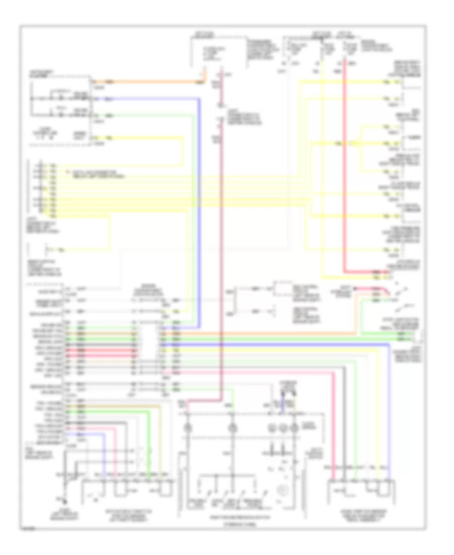
CRUISE CONTROL
Cruise Control Wiring Diagram for Hyundai Azera Limited 2010
List of elements for Cruise Control Wiring Diagram for Hyundai Azera Limited 2010:
- (+)
- (-)
- (behind right side of dash) atm key lock control module
- (left rear of engine compt)
- A/c control module
- Abs
- Abs control module (left rear of engine compt)
- Abs/esc buff wheel input
- Accel position sensor (above accelerator pedal assembly)
- Aps 1 ground
- Aps 1 power
- Aps 1 sig
- Aps 2 ground
- Aps 2 power
- Aps 2 sig
- Audio
- Av amp module (right side of trunk)
- B/up fuse 10a
- Bcm (behind left kick panel)
- Brake lamp
- Brake switch
- Can- cel
- Clg-a
- Clg-b
- Clock spring
- Cruise ind
- Cruise main
- Cruise set ind
- Cruise sw
- Data link connector (below left side of dash)
- Ecu (ig1) fuse 10a
- Engine compartment junction block
- Esc
- Esc control module
- Etc motor & throttle position sensor (on throttle body)
- Etc motor +
- Etc motor -
- F55-b
- F57-b
- Glg01 (left rear of engine compt)
- Hot at all times
- Hot in on or start
- I/p-f
- Ill
- Instrument cluster
- Interior lights system
- Jc01
- Je01
- Je02
- Joint connector e-1 (behind right side of dash)
- Joint connector m-10 (under front of center console)
- Joint connector m-2 (behind left center of dash)
- M14
- M28-c
- M32-a
- M32-b
- M45-b
- M50-b
- M58-a
- Micro controller
- Module 2 fuse 10a
- Mts module (center of dash)
- Multi- function switch
- Nca
- On/start in
- Passenger compartment junction block (under left end of dash)
- Pcm (left rear of engine compt)
- Pnk
- Premium amp (behind trim, at right side of trunk)
- Rear curtain module (under front of center console)
- Red
- Resume/ accel
- Right cruise remocon switch
- Sensor ground
- Set/ coast
- Shift interlock system
- Speed input
- Steering wheel
- Stop fuse 15a
- Stop lamp switch (above brake pedal, on bracket)
- Tire pressure monitoring module (under front of center console)
- Tps 1 ground
- Tps 1 power
- Tps 1 sig
- Tps 2 ground
- Tps 2 power
- Tps 2 sig
- Vehicle spd out
 English