CRUISE CONTROL
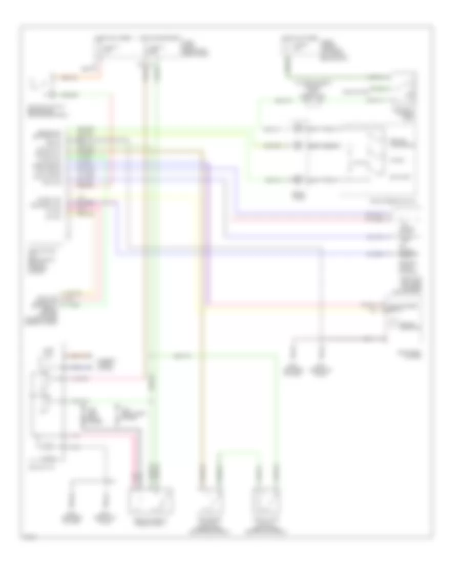
Cruise Control Wiring Diagram, A/T for Infiniti I30 t 1998

List of elements for Cruise Control Wiring Diagram, A/T for Infiniti I30 t 1998:
- (in fuse & fusible link box) joint connector 4
- Air valve
- Air valve solenoid
- Anti-theft system
- Ascd brake switch (behind dash, above brake pedal)
- Ascd control unit (behind dash, right of steering column)
- Ascd hold relay (in relay box 2)
- Ascd pump (left rear of engine compartment)
- Ascd steering switch
- Ascd switch
- Brake nc sw
- Cancel
- Clock (hcc)
- Cruise indicator
- Cruise lamp
- Cruise signal
- Data link connector for consult (behind left side of dash, behind fuse box cover)
- Fuse 10 15a
- Fuse 12 7.5a
- Fuse 17 10a
- Fuse 64 10a
- Fuse and fusible link block
- Fuse block
- G100 (left front fender)
- G101 (right front fender)
- G120 (right side of engine)
- G202 (left side of dash)
- G203 (right kick panel)
- Ground
- Horn relay (in relay box 2)
- Horn system
- Hot at all times
- Hot in on or start
- Illum.
- Inhibitor relay (in relay box 2)
- Inhibitor switch (on left rear side of transaxle)
- Instrument cluster
- Interior lights system
- Main switch
- Nca
- Od cancel sig
- Od cut signal
- Off
- On ind.
- Pnk
- Pump power
- Release valve
- Release valve solenoid
- Res/acc sw set/coast sw
- Resume/ accelerate
- Rx (hcc)
- Set/coast
- Speed sensor
- Spiral cable
- Stop lamp switch (behind dash above brake pedal)
- Theft warning relay (in relay box 1)
- Tk (hcc)
- Transmission control module (at front center of console)
- Vacuum motor
- Vehicle speed output
Cruise Control Wiring Diagram, M/T for Infiniti I30 t 1998
List of elements for Cruise Control Wiring Diagram, M/T for Infiniti I30 t 1998:
- (in fuse & fusible link box) joint connector 4
- Air valve
- Air valve solenoid
- Ascd brake switch (behind dash, above brake pedal)
- Ascd clutch switch (behind dash, above clutch pedal)
- Ascd control unit (behind dash, right of steering column)
- Ascd hold relay (in relay box 1)
- Ascd pump (left rear of engine compartment)
- Ascd steering switch
- Ascd switch
- Brake nc sw
- Cancel
- Clock (hcc)
- Cruise indicator
- Cruise lamp
- Data link connector for consult (behind left side of dash, behind fuse box cover)
- Fuse & fusible link block left side of engine compt)
- Fuse 10 15a
- Fuse 12 7.5a
- Fuse 64 10a
- Fuse block (behind left side of dash)
- G100 (left front fender)
- G101 (right front fender)
- G202 (left side of dash)
- G203 (right kick panel)
- Ground
- Horn relay (in relay box 2)
- Horn system
- Hot at all times
- Hot in on or start
- Illum.
- Instrument cluster
- Interior lights system
- Main switch
- Nca
- Off
- On ind
- Pnk
- Pump common
- Release valve
- Release valve solenoid
- Res/acc sw set/coast sw
- Resume/ accelerate
- Rx (hcc)
- Set/coast
- Speed sensor
- Spiral cable
- Stoplight switch (behind dash above brake pedal)
- Tk (hcc)
- Vacuum motor
- Vehicle speed output