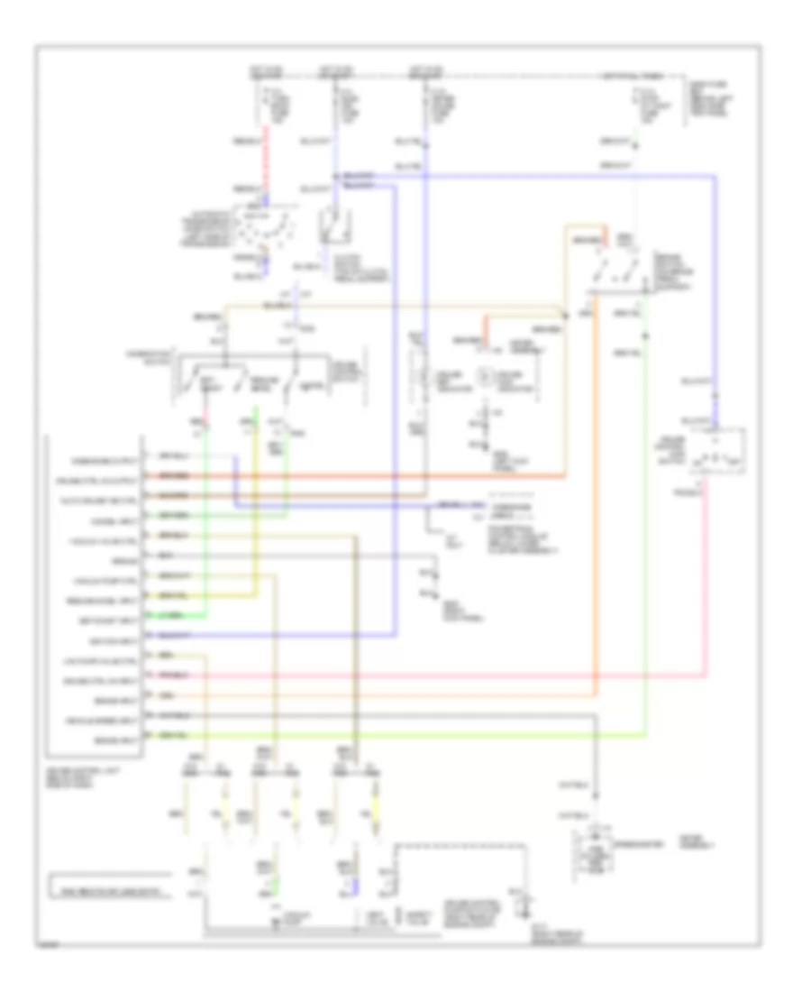
CRUISE CONTROL
Cruise Control Wiring Diagram for Isuzu Trooper Limited 1996
List of elements for Cruise Control Wiring Diagram for Isuzu Trooper Limited 1996:
- "auto cruise" ind ctrl
- A/t
- A/t only
- Automatic transmission mode switch (left side of transmission)
- B-52
- Brake input
- Brake switch (on brake pedal support)
- C-10 meter gauge fuse 10a
- C-14 stop a/t cont fuse 15a
- C-3
- C-3 turn back fuse 15a
- C-4 elec. ign. fuse 10a
- Cancel
- Cancel input
- Clutch switch (top of clutch pedal support)
- Combination switch
- Cruise control main switch
- Cruise control pump/actuator (right rear of engine compt)
- Cruise control switch
- Cruise control unit (below right side of dash)
- Cruise ctrl on input
- Cruise ctrl on output
- Cruise main indicator
- Cruise set indicator
- Dash fuse box (behind left dash side trim panel
- Disengage input
- Disengage output
- F10
- G117 (right rear of engine compt)
- G200 (left kick panel)
- G203 (right kick panel)
- Ground
- Hot at all times
- Hot in on or start
- I-10
- I-40
- Ignition input
- M/t
- Meter assembly
- Off
- Powertrain control module (below lower cluster assembly)
- Pulses per mile
- Red
- Resume/ accel
- Resume/accel input
- Rke: remote keyless entry
- Safety valve
- Set/ coast
- Set/coast input
- Speedometer
- Vac pump/valve ctrl
- Vacuum pump
- Vacuum pump ctrl
- Vacuum valve ctrl
- Vehicle speed input
- Vent valve
- W/ rke
- W/o rke
 English