DEFOGGERS
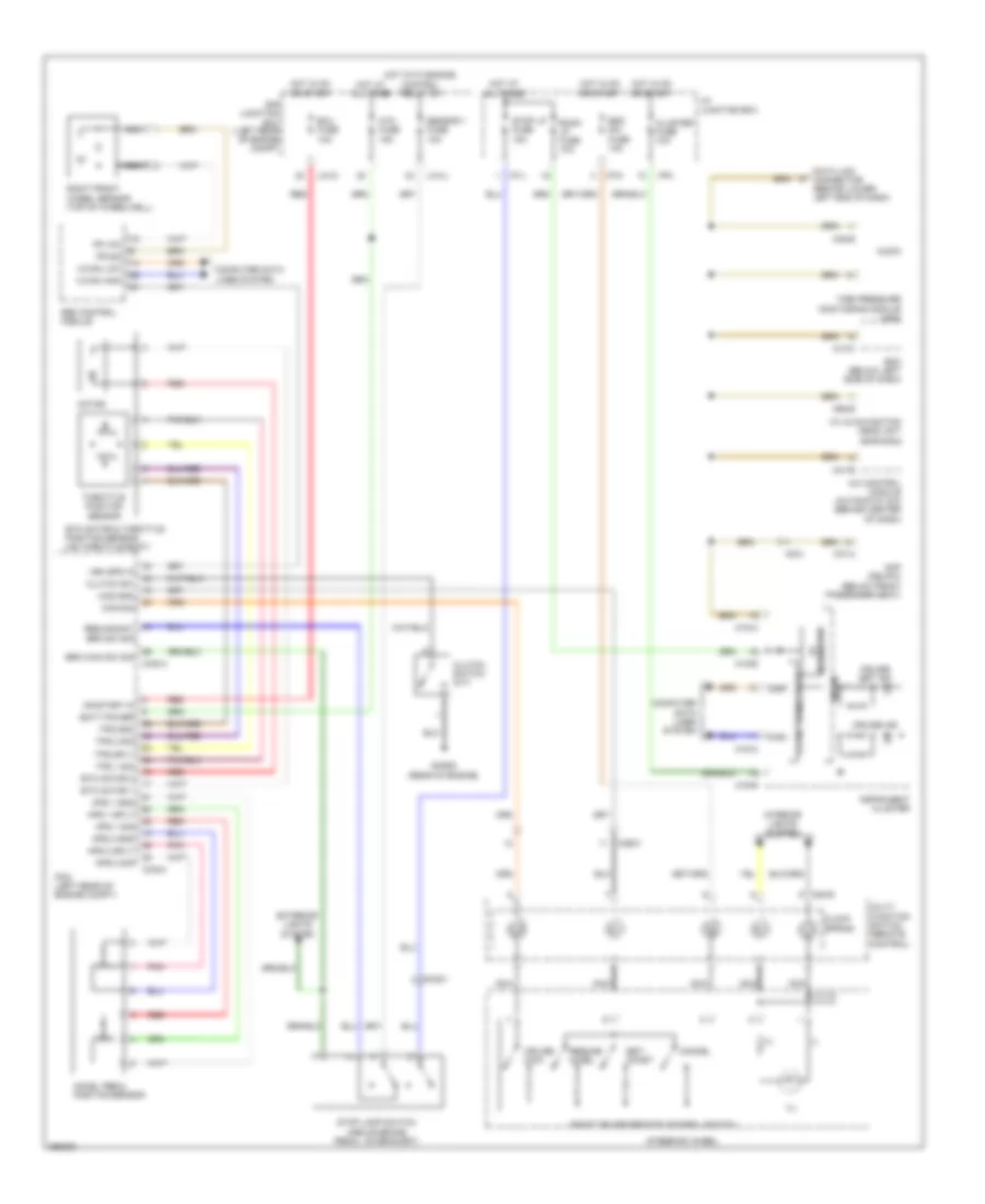
Defogger Wiring Diagram for Hyundai XG350 2002
List of elements for Defogger Wiring Diagram for Hyundai XG350 2002:
- (+)
- (-)
- A/c control module (automatic a/c) (behind center of dash)
- A/v & navigation head unit (with a/v)
- Accel pedal position sensor
- Amp (delphi) (below front passenger seat)
- Aps 1 gnd
- Aps 1 sig
- Aps 1 sply
- Aps 2 gnd
- Aps 2 sig
- Aps 2 sply
- Atm fuse 15a
- Audio
- Batt power
- Bcm (below left side of dash)
- Brk main sw sig
- Brk sw sig
- C-can high
- C-can low
- C-can transceiver
- Cancel
- Ccs gnd
- Ccs sig
- Chg-a
- Chg-k
- Clock spring
- Cluster fuse 10a
- Clutch sw
- Clutch switch (m/t)
- Computer data lines system
- Cruise ind
- Cruise main
- Cruise set ind
- Data link connector (behind lower left end of dash)
- E/r junction box (left rear of engine compt)
- Ecu fuse 10a
- Esc control module
- Esc sw fuse 10a
- Etc motor & throttle position sensor (on throttle body)
- Etc motor 1
- Etc motor 2
- Exterior lights system
- F37-a
- Fr sig
- Fr vcc
- Ghg02 (rear of engine)
- High
- Hot at all times
- Hot in on or start
- Hot with engine control relay on
- I/p junction box
- I/p-j
- I/p-k
- I/p-m
- Ill
- Instrument cluster
- Interior lights system
- Low
- M13-c
- M15-a
- M15-b
- M20-r
- M41-b
- M45-e
- M62-e
- Mc221
- Mc231
- Mf31
- Micom
- Motor
- Multi- function switch (remote control)
- Nca
- On/start in
- Pcm (left rear of engine compt)
- Pnk
- Red
- Redundant
- Regulator 5v
- Resume/ accel
- Right cruise remote control switch
- Right front wheel sensor (top of wheelwell)
- Room lp fuse 10a
- Sensor 1 fuse 10a
- Set/ coast
- Steering wheel
- Stop lamp switch (above brake pedal, on bracket)
- Stop lp fuse 15a
- Throttle position sensor
- Tire pressure monitoring module (usa)
- Tps 1 sig
- Tps 2 sig
- Tps gnd
- Tps sply
- U/h-c
- U/h-u
- Veh spd in
 English