ELECTRONIC POWER STEERING
Electronic Power Steering Wiring Diagram for Hyundai XG350 2002
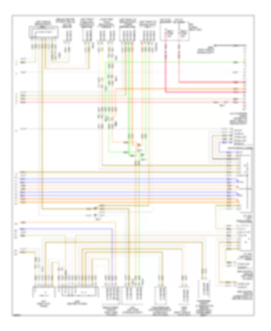
List of elements for Electronic Power Steering Wiring Diagram for Hyundai XG350 2002:
- (behind center of front grille)
- (in battery pack) bms control module
- (left front of engine compt) hybrid control unit
- (left front of engine compt) mcu
- (left front wheelwell) electric oil pump unit
- (left side of engine compt)
- (right side of
- (upper right end of dash)
- 4p out
- Active air flap
- B-can hi
- B-can lo
- B-can low
- C-can hi
- C-can high
- C-can low
- Chg-a
- Chg-k
- Chg34-s
- E/r fuse & relay box
- E64-b
- Ec11
- Ee01
- Em11
- Em61
- Eps control module (left side of dash)
- Esc 2 fuse 30a
- Esc 3 fuse 10a
- Ff01
- Ge04 (right side of engine compt)
- H-can hi
- H-can high
- H-can lo
- H-can low
- Hot at all times
- Hot in on or start
- Hvac unit)
- Instrument cluster
- J/c jm02 (left side of dash)
- J/c jm05 (center of dash)
- Je03
- Jf01 (right kick panel)
- Jm06 (center of dash)
- M-can high
- M-can low
- Mf11
- Mf61
- Monitoring module
- Multipurpose check connector (right rear of engine compt)
- Passenger weight classification sensor (under front passenger's seat)
- Pcm (left side of engine compt)
- Pnk
- Rear camera module (right side of dash)
- Red
- Srs control module (under front of center console)
- Tire pressure
- Vess unit
 English