ENGINE PERFORMANCE
3.3L
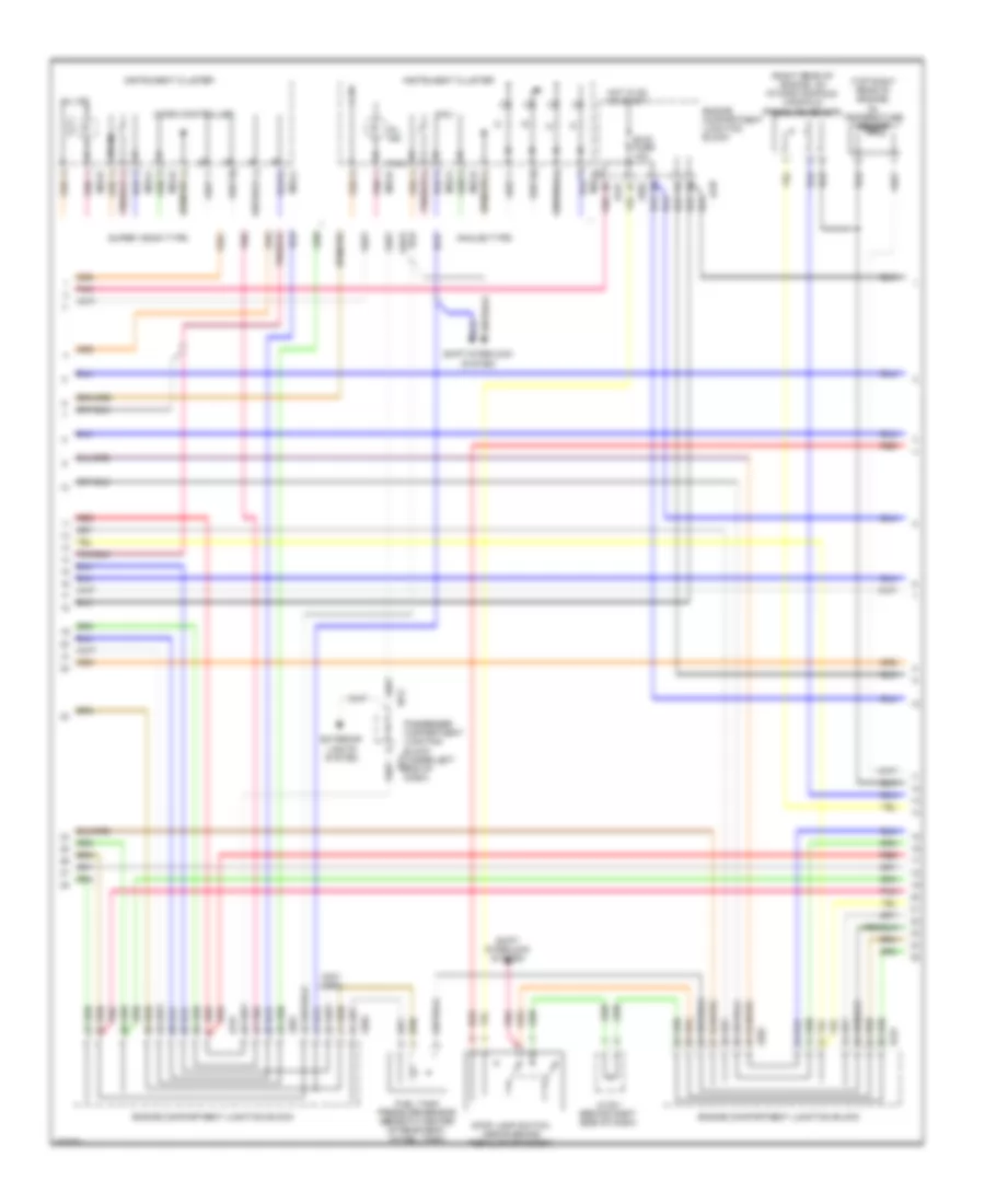
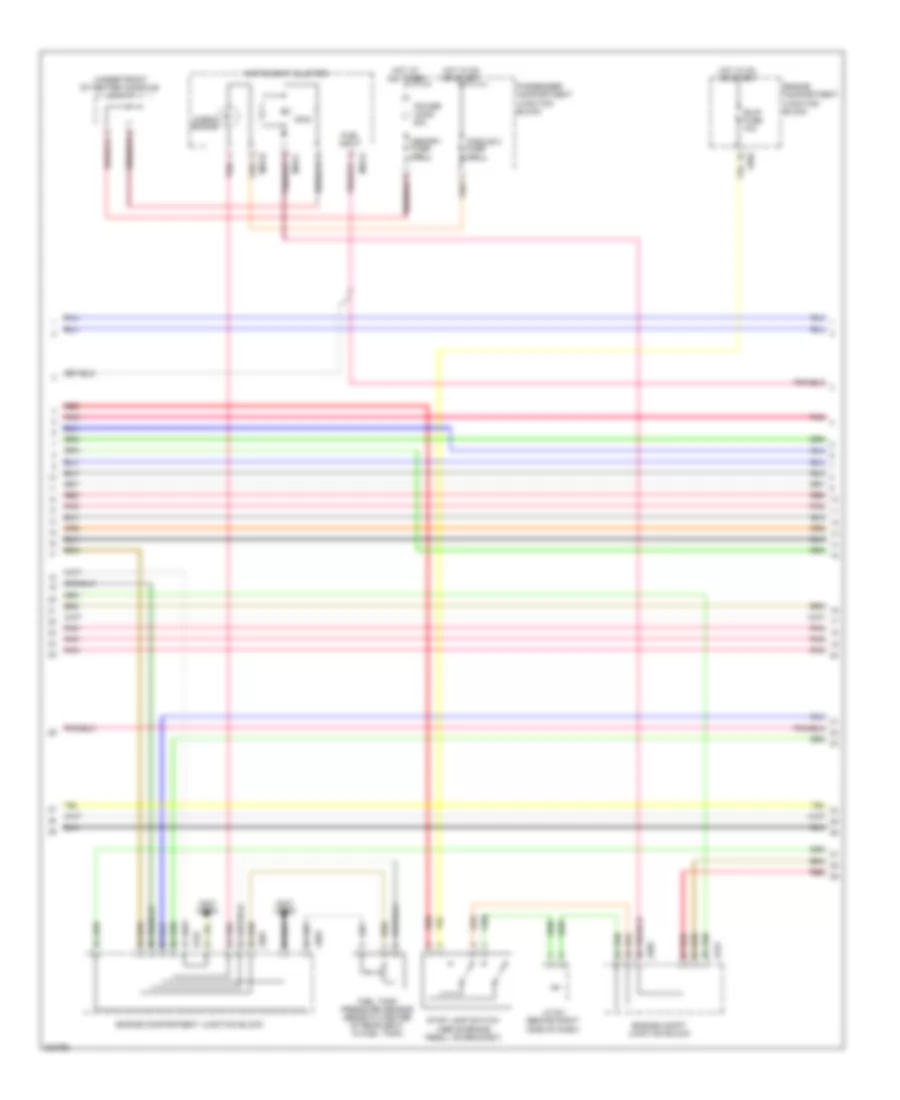
3.3L, Engine Performance Wiring Diagram, Early Production (1 of 5) for Hyundai Azera GLS 2010

List of elements for 3.3L, Engine Performance Wiring Diagram, Early Production (1 of 5) for Hyundai Azera GLS 2010:
- (not used)
- (on fuel filler neck)
- A/c relay ctrl
- Abs/esc
- Afs
- Air conditioning system
- Analog fuel level in
- Anti-lock brakes system cruise control system
- Anti-theft system
- Aps 1 ground
- Aps 1 power
- Aps 1 signal
- Aps 2 ground
- Aps 2 power
- Aps 2 signal
- Ats
- Ats ground
- Battery voltage
- Blower switch input
- Can high
- Can low
- Canister close valve
- Ccv
- Computer data lines system
- Computer data lines system air conditioning system
- Cooling fans system
- Cruise control system
- Cruise ind
- Cruise set ind
- Ecu fuse 10a
- Ecu fuse 30a
- Eng ctrl rly ctrl
- Eng ctrl rly on pwr
- Eng spd out (tach)
- Engine compartment junction block
- Engine control relay
- F/pump fuse 20a
- Fan control
- Fuel consumption
- Fuel pump relay
- Fuel pump rly ctrl
- Fuel sender & fuel pump motor (beneath center of rear seat, in fuel tank)
- Fuel sender a
- Fuel sender b
- Gf02 (on left "c" pillar)
- Glg-a
- Glg01 (left rear of engine compt)
- Hot at all times
- Immo ind
- Immo signal
- Ind ctrl mil
- Jc01
- Je01
- Je02
- K line
- Mass air flow sensor (left rear of engine compt, in air intake duct)
- Pcm (left rear of engine compt)
- Pcsv
- Pnk
- Power steering pressure sensor (right front of engine)
- Purge control solenoid valve (on rear of intake manifold)
- Pwm sig
- Red
- Sensor ground
- Sensor sply (5v)
- Signal
- Snsr 1 fuse 15a
- Snsr 2 fuse 15a
- Thrott pos pwm out
- To ign coil fuse (diagram 4 of 5)
- To snsr 3 fuse (diagram 4 of 5)
- Variable intake manifold valve (top front of engine)
- Vehicle speed output
- Viv
- Wheel spd sens hi
- Wheel spd sens low
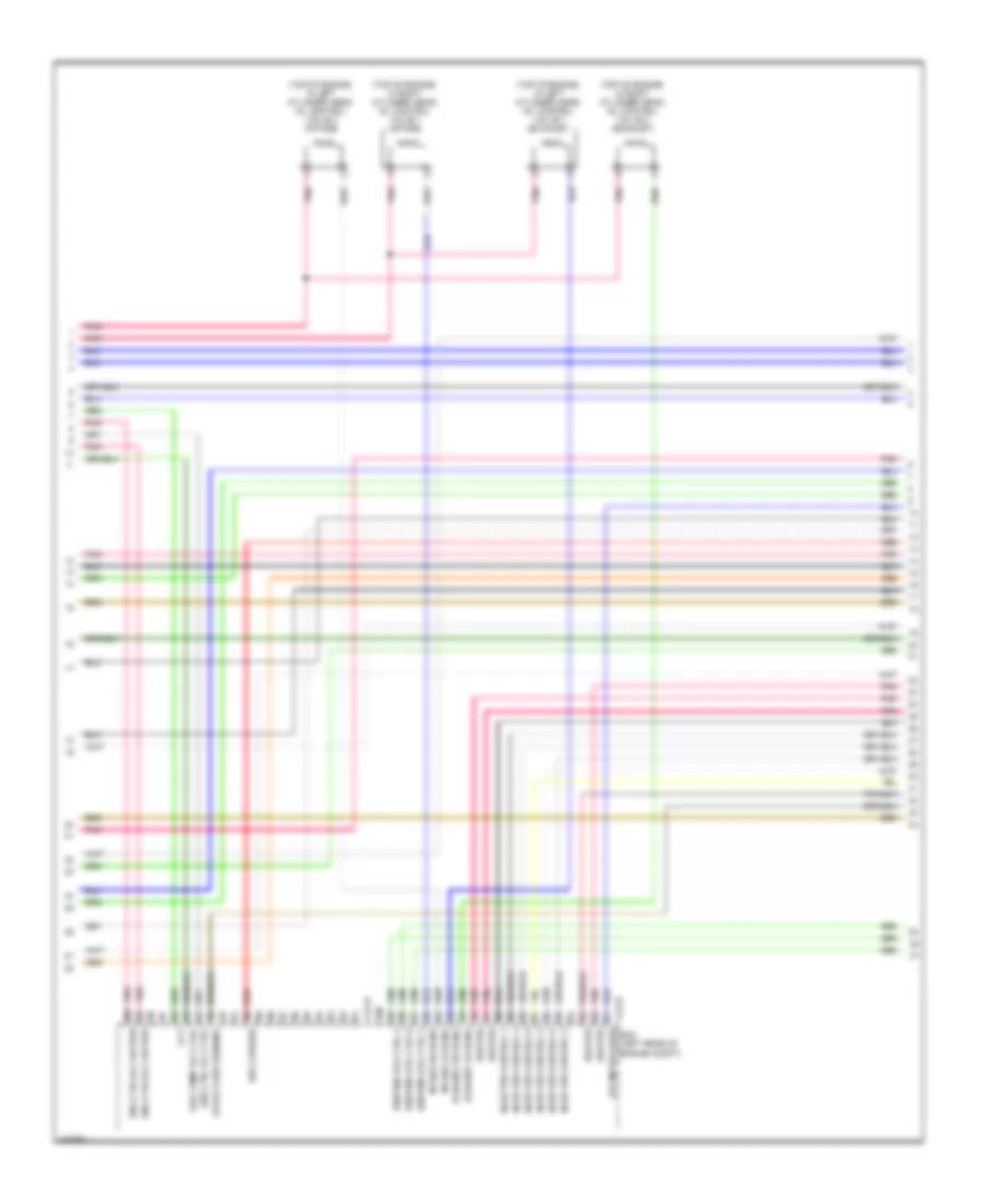
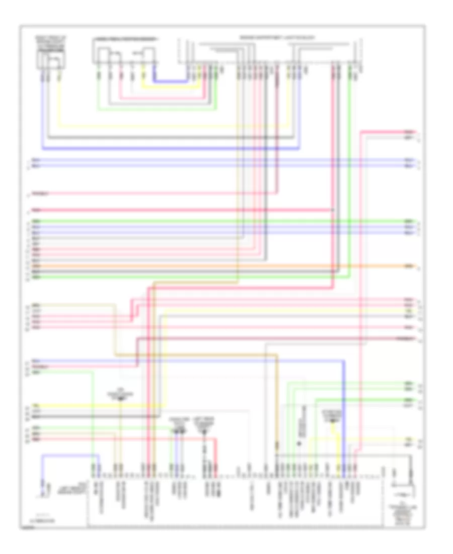
3.3L, Engine Performance Wiring Diagram, Early Production (2 of 5) for Hyundai Azera GLS 2010
List of elements for 3.3L, Engine Performance Wiring Diagram, Early Production (2 of 5) for Hyundai Azera GLS 2010:
- (not used)
- (top of engine, in left cylinder head) oil control valve 2
- (top of engine, in right cylinder head) oil control valve 1
- (top of transaxle) transaxle range switch
- A/c pressure transducer (right front of engine compt)
- Accel position sensor (above accelerator pedal assembly)
- Down shift
- Engine compartment junction block
- Engine coolant temperature sensor & sender (on rear of engine)
- Hot in on or start
- I/p-f
- Instrument cluster system
- Jc01
- Je01
- Je02
- Manual
- Module 2 fuse 10a
- Nca
- Normal
- Passenger compartment junction block (under left end of dash)
- Pnk
- Red
- Select switch
- Sender
- Sensor
- Sport mode switch
- Starting/ charging system
- Up shift
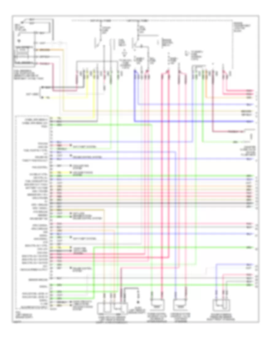
3.3L, Engine Performance Wiring Diagram, Early Production (3 of 5) for Hyundai Azera GLS 2010
List of elements for 3.3L, Engine Performance Wiring Diagram, Early Production (3 of 5) for Hyundai Azera GLS 2010:
- (not used)
- (right rear of engine, on intake manifold) manifold pressure sensor
- (top right rear of engine) oil temperature sensor
- Analog type
- B/up fuse 10a
- Engine compartment junction block
- Exterior lights system
- Fuel tank pressure sensor (beneath center of rear seat, in fuel tank)
- Hot in on or start
- I/p-g
- Instrument cluster
- J/c e-1 (behind right side of dash)
- Jc01
- Je01
- Je02
- M32-a
- M32-b
- Mcu
- Micro controller
- Mil ind
- Passenger compartment junction block (under left end of dash)
- Pnk
- Pwm
- Red
- Shift interlock system
- Stop lamp switch (above brake pedal, on bracket)
- Super vision type
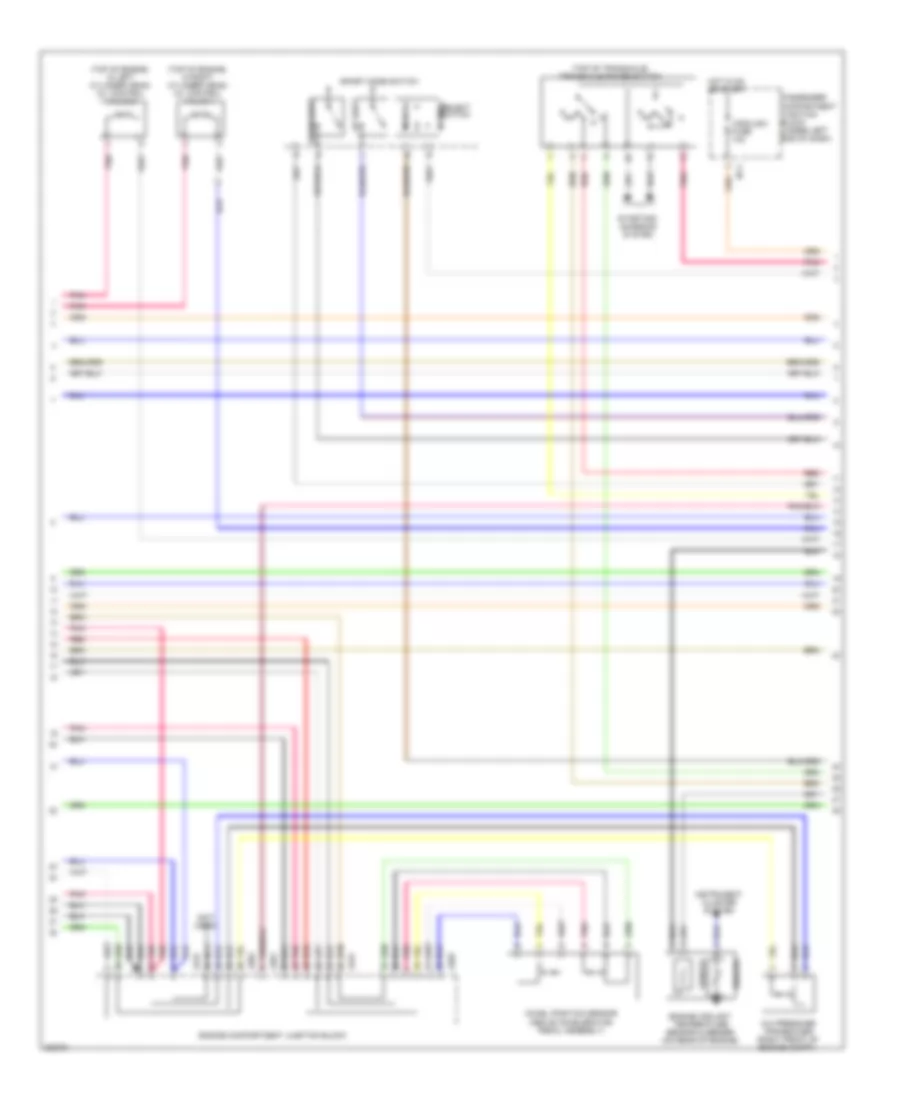
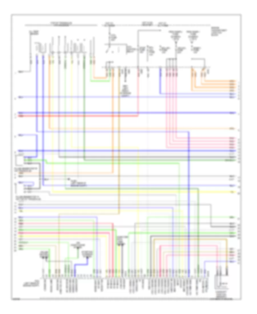
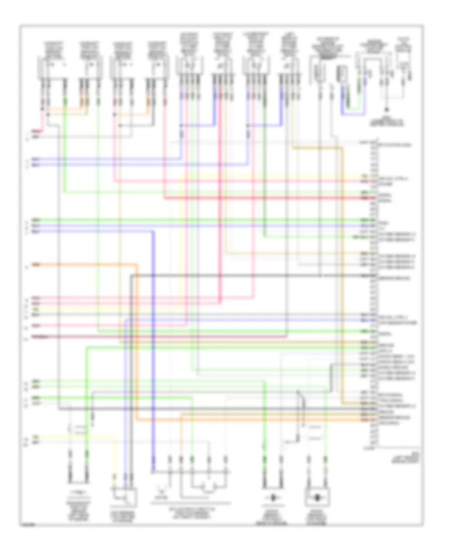
3.3L, Engine Performance Wiring Diagram, Early Production (4 of 5) for Hyundai Azera GLS 2010
List of elements for 3.3L, Engine Performance Wiring Diagram, Early Production (4 of 5) for Hyundai Azera GLS 2010:
- "d" input
- "n" input
- "p" input
- "r" input
- (ig1) fuse 10a
- (top of transaxle) atm solenoid
- A/c sw on in
- Air conditioning system
- Atm control relay
- Atm ctrl rly
- Atm fuse 20a
- Brake lamp
- Brake sw
- Camshaft position sensor 2 (top rear of engine)
- Can high
- Can low
- Computer data lines system
- Coolant sens
- Cps 1 ground
- Cps 1 signal
- Cps 2 ground
- Cps 2 power
- Cps 2 signal
- Cps high
- Cruise control system
- Cruise sw
- Down shift
- Ecu
- Ecu (b+) fuse 10a
- Engine compartment junction block
- Etc motor +
- Etc motor -
- From snsr 1 fuse (diagram 1 of 5)
- From snsr 2 fuse (diagram 1 of 5)
- Ge01 (left front of engine compt)
- Generator
- Glg-a
- Glg-b
- Glg01 (left rear of engine compt)
- Hot at all times
- Hot in on or start
- Ign coil 6
- Ign coil fuse 20a
- Input
- Jc01
- Je01
- Je02
- Map power
- Map signal
- Nca
- Oil temp sens
- Oil temp sensor
- On/start in
- Output
- Pcm (left rear of engine compt)
- Pnk
- Pulse generator "a" (on top of transaxle)
- Pulse generator "b" (on transaxle)
- Red
- Select sw
- Sensor gnd
- Shield gnd
- Snsr 3 fuse 10a
- Starting/ charging system
- Stop fuse 15a
- Tps 1 ground
- Tps 1 power
- Tps 2 power
- Up shift
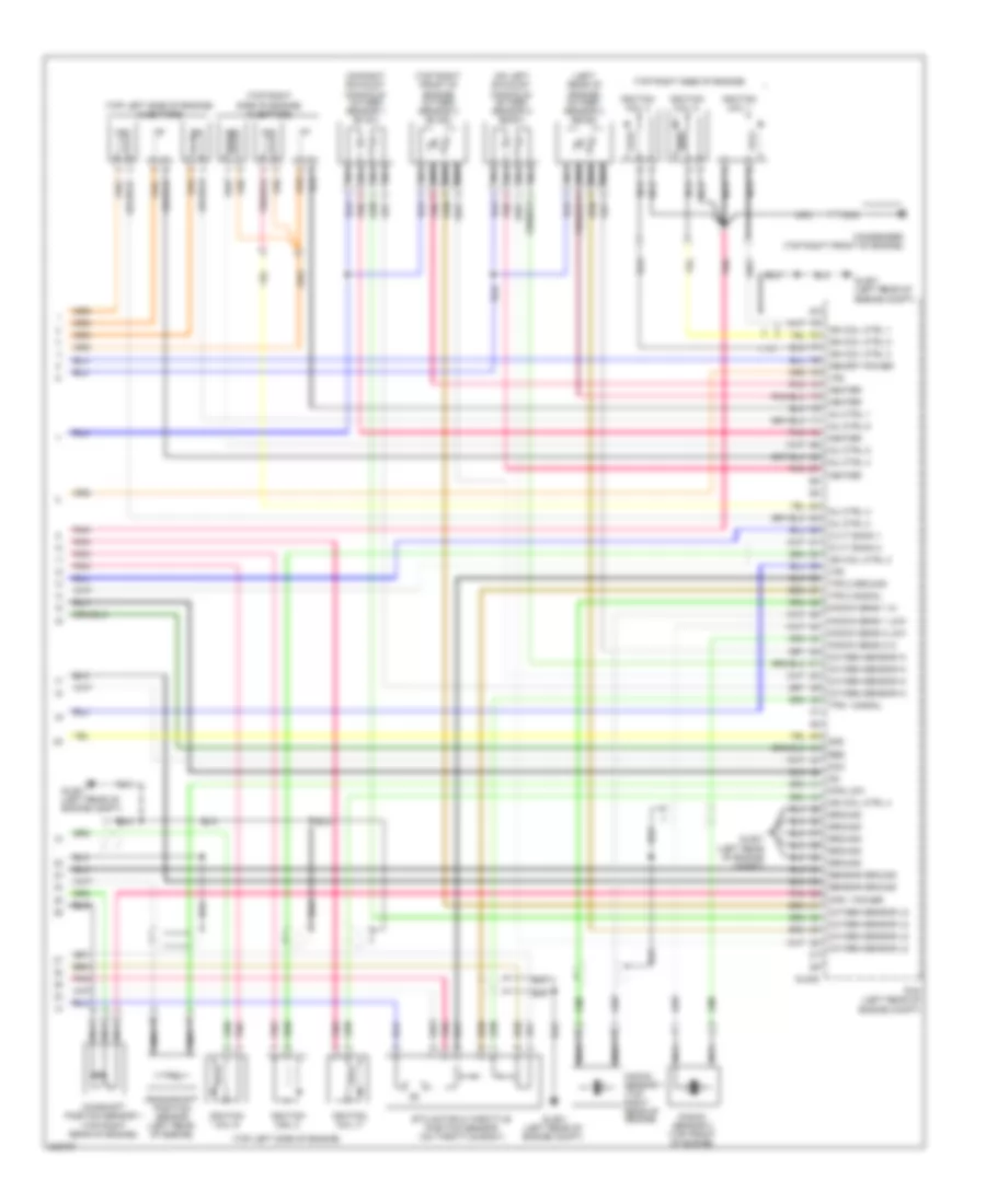
3.3L, Engine Performance Wiring Diagram, Early Production (5 of 5) for Hyundai Azera GLS 2010
List of elements for 3.3L, Engine Performance Wiring Diagram, Early Production (5 of 5) for Hyundai Azera GLS 2010:
- (left rear of engine) oxygen sensor 4 (b2/s2)
- (on left exhaust manifold) oxygen sensor 2 (b2/s1)
- (on right exhaust manifold) oxygen sensor 1 (b1/s1)
- (top left side of engine)
- (top left side of engine) injectors
- (top right front of engine) oxygen sensor 3 (b1/s2)
- (top right side of engine)
- (top right side of engine) injectors
- 2nd
- Camshaft position sensor 1 (top right rear of engine)
- Condenser (top right front of engine)
- Cps 1 power
- Cps low
- Crankshaft position sensor (left rear of engine)
- Cvvt bank 1
- Cvvt bank 2
- Dcc
- Etc motor & throttle position sensor (on throttle body)
- Glg-b
- Glg01 (left rear of engine compt)
- Ground
- Heater
- Ign coil ctrl 1
- Ign coil ctrl 2
- Ign coil ctrl 3
- Ign coil ctrl 4
- Ign coil ctrl 5
- Ignition coil 1
- Ignition coil 2
- Ignition coil 3
- Ignition coil 4
- Ignition coil 5
- Ignition coil 6
- Inj ctrl 1
- Inj ctrl 2
- Inj ctrl 3
- Inj ctrl 4
- Inj ctrl 5
- Inj ctrl 6
- Knock sens 1 hi
- Knock sens 1 low
- Knock sens 2 hi
- Knock sens 2 low
- Knock sensor 1 (top right rear of engine)
- Knock sensor 2 (top front of engine)
- Memory power
- Nca
- Oxygen sensor hi
- Oxygen sensor lo
- Pcm (left rear of engine compt)
- Pnk
- Red
- Sensor ground
- Tps 1 signal
- Tps 2 ground
- Tps 2 signal
- Vfs
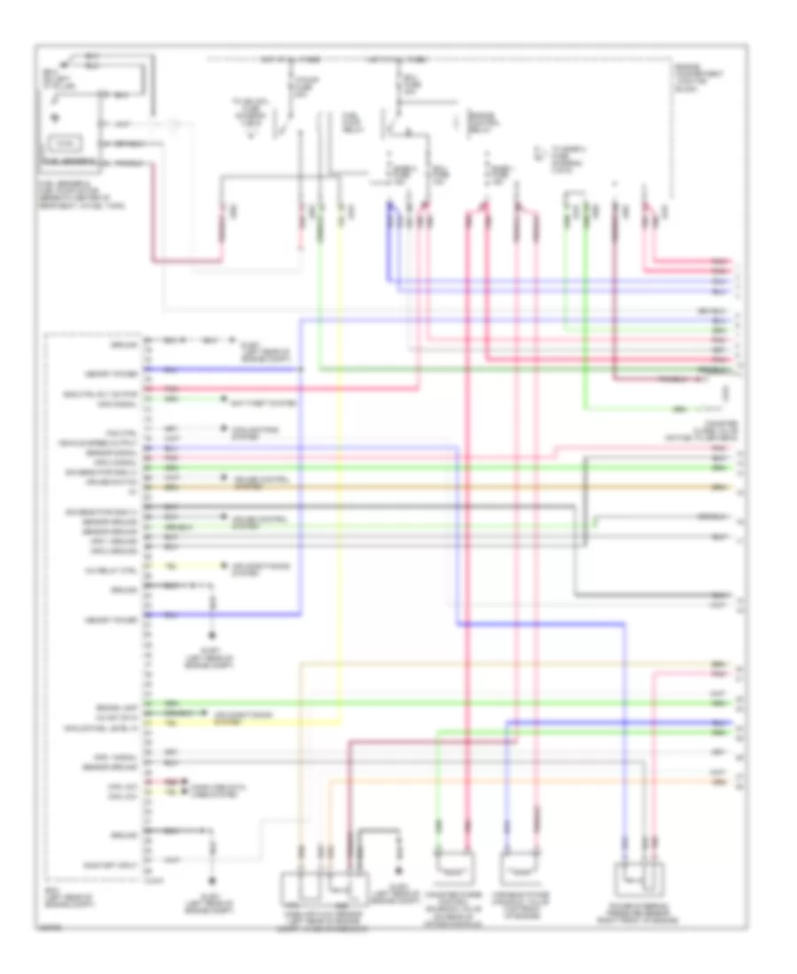
3.3L, Engine Performance Wiring Diagram, Late Production (1 of 6) for Hyundai Azera GLS 2010
List of elements for 3.3L, Engine Performance Wiring Diagram, Late Production (1 of 6) for Hyundai Azera GLS 2010:
- (left rear of engine compt)
- (on rear of intake manifold)
- A/c relay ctrl
- A/c sw on in
- Afs
- Air conditioning system
- Analog fuel level in
- Anti-theft system
- Aps 1 ground
- Aps 1 signal
- Aps 2 ground
- Aps 2 signal
- Ats
- Brake lamp
- Can low
- Canister close valve (on fuel filler neck)
- Canister purge control solenoid valve
- Clg-a
- Computer data lines system
- Cooling fans system
- Cruise control system
- Cruise switch
- Ecm (left rear of engine compt)
- Ecu fuse 10a
- Ecu fuse 30a
- Eng ctrl rly on pwr
- Engine compartment junction block
- Engine control relay
- F/pump fuse 20a
- Fan ctrl
- Fuel pump relay
- Fuel sender & fuel pump motor (beneath center of rear seat, in fuel tank)
- Fuel sender b
- Gf02 (on left "c" pillar)
- Glg01
- Glg01 (left rear of engine compt)
- Ground
- Hot at all times
- Immo signal
- Jc01
- Je01
- Je02
- Mass air flow sensor (left rear of engine compt, in air intake duct)
- Memory power
- On/start input
- Pnk
- Power steering pressure sensor (right front of engine)
- Red
- Sensor ground
- Sensor signal
- Sig sens pwr gnd (v)
- Snsr 1 fuse 15a
- Snsr 2 fuse 15a
- To ign coil fuse (diagram 3 of 6)
- To snsr 3 fuse (diagram 3 of 6)
- Variable intake manifold valve (top front of engine)
- Vehicle speed output
3.3L, Engine Performance Wiring Diagram, Late Production (2 of 6) for Hyundai Azera GLS 2010
List of elements for 3.3L, Engine Performance Wiring Diagram, Late Production (2 of 6) for Hyundai Azera GLS 2010:
- (top of engine, in left cylinder head) oil control valve 1 (exhaust)
- (top of engine, in left cylinder head) oil control valve 2 (intake)
- (top of engine, in right cylinder head) oil control valve 1 (intake)
- (top of engine, in right cylinder head) oil control valve 2 (exhaust)
- Aps 2 power
- Ccv
- Clg-a
- Clg-b
- Ecm (left rear of engine compt)
- Eng ctrl rly ctrl
- Eng ctrl rly on pwr
- Etc motor (low)
- Exhaust lh bank
- Exhaust rh bank
- Fuel pump rly ctrl
- Heater
- Ignition coil ctrl 2
- Ignition coil ctrl 4
- Ignition coil ctrl 6
- Injector control 1
- Injector control 2
- Injector control 3
- Injector control 4
- Injector control 5
- Injector control 6
- Intake lh bank
- Intake rh bank
- Pnk
- Red
- Start over running
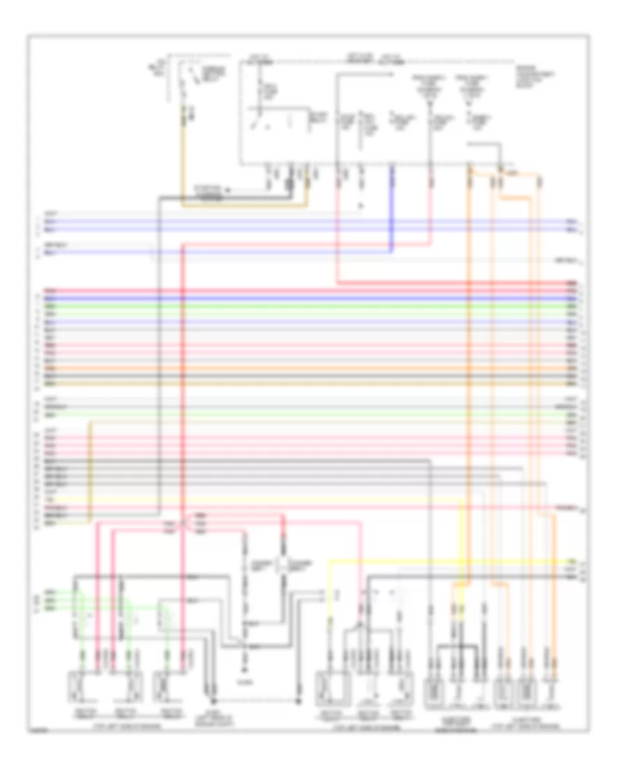
3.3L, Engine Performance Wiring Diagram, Late Production (3 of 6) for Hyundai Azera GLS 2010
List of elements for 3.3L, Engine Performance Wiring Diagram, Late Production (3 of 6) for Hyundai Azera GLS 2010:
- (top left side of engine)
- Clg18-1
- Clg18-2
- Clg18-3
- Clg18-4
- Clg18-5
- Clg18-6
- Conden- ser 1
- Conden- ser 2
- Ecu (b+) fuse 10a
- Ecu (ig1) fuse 10a
- Engine compartment junction block
- Engine compt)
- From snsr 1 fuse (diagram 1 of 6)
- From snsr 2 fuse (diagram 1 of 6)
- Glg01 (left rear of
- Glg02
- Hot at all times
- Hot in on or start
- Icm relay box
- Ign 2 fuse 40a
- Ign coil fuse 20a
- Ignition coil 1
- Ignition coil 2
- Ignition coil 3
- Ignition coil 4
- Ignition coil 5
- Ignition coil 6
- Injectors
- Injectors (top right side of engine)
- Jc01
- Je01
- Je02
- M01-b
- Nca
- Parking/ neutral relay
- Pnk
- Red
- Snsr 3 fuse 10a
- Start relay
- Starting/ charging system
- Stop fuse 15a
3.3L, Engine Performance Wiring Diagram, Late Production (4 of 6) for Hyundai Azera GLS 2010
List of elements for 3.3L, Engine Performance Wiring Diagram, Late Production (4 of 6) for Hyundai Azera GLS 2010:
- (not used)
- (under front of center console) j/c m-17
- B/up fuse 10a
- Check engine
- Engine compartment junction block
- Engine compt junction block
- Fuel input
- Fuel tank pressure sensor (beneath center of rear seat, in fuel tank)
- Hot at all times
- Hot in on or start
- Immo
- Instrument cluster
- J/c e-1 (behind right side of dash)
- Jc01
- Je01
- Je02
- M32-a
- M32-b
- M32-c
- Memory fuse 15a
- Module 2 fuse 10a
- Nca
- Passenger compartment junction block
- Pnk
- Power conn 30a
- Red
- Stop lamp switch (above brake pedal, on bracket)
3.3L, Engine Performance Wiring Diagram, Late Production (5 of 6) for Hyundai Azera GLS 2010
List of elements for 3.3L, Engine Performance Wiring Diagram, Late Production (5 of 6) for Hyundai Azera GLS 2010:
- (left rear of engine compt)
- (right front of engine compt)
- A/c pressure transducer
- Accel pedal position sensor
- Air conditioning system
- Alternator
- Alternator (fr)
- Analog fuel lvl in
- Anti-lock brakes system
- Aps1 power
- Ats signal
- Blower sw in
- Brake sw
- Can high
- Clg-a
- Clg-b
- Clg06
- Computer data lines system
- Cps hi
- Crank request
- Engine compartment junction block
- Glg01
- Ground
- Ign coil ctrl 1
- Immo ind
- Jc01
- Je02
- Knock sensor 2 hi
- Map sensor sig
- Mil ind
- Oil temp sens gnd
- Oil temp sens sig
- Oil temperature sensor (top right rear of engine)
- Pcm (left rear of engine compt)
- Pnk
- Power
- Pwm
- Red
- Sig sens pwr gnd(v)
- Signal
- Starting/ charging system
- Tps 1 signal
- Tps power
- Vehicle spd in
3.3L, Engine Performance Wiring Diagram, Late Production (6 of 6) for Hyundai Azera GLS 2010
List of elements for 3.3L, Engine Performance Wiring Diagram, Late Production (6 of 6) for Hyundai Azera GLS 2010:
- (auto) a/c control module
- (left rear of engine) oxygen sensor 4 (b2/s2)
- (lower right front of engine) oxygen sensor 2 (b2/s1)
- (on rear of engine) engine coolant temperature sensor & sender
- (on right exhaust manifold) oxygen sensor 1 (b1/s1)
- (top right front of engine) oxygen sensor 3 (b1/s2)
- Afs signal
- Camshaft position sensor 1 (exhaust)
- Camshaft position sensor 1 (intake)
- Camshaft position sensor 2 (exhaust)
- Camshaft position sensor 2 (intake)
- Clg-b
- Cps lo
- Crankshaft position sensor (left rear of engine)
- Ecm (left rear of engine compt)
- Ects signal
- Engine compartment junction block
- Etc motor & throttle position sensor (on throttle body)
- Etc motor (high)
- Gm01 (under front of center console)
- Ground
- Ign coil ctrl 3
- Ign coil ctrl 5
- Jc01
- Je01
- Knock sens 1 low
- Knock sens 2 low
- Knock sensor 1 (top right rear of engine)
- Knock sensor 2 (top front of engine)
- M50-b
- Map sensor (top center of engine)
- Map sensor power
- Motor
- Nca
- Oxygen sensor hi
- Oxygen sensor lo
- Pcsv
- Pnk
- Power
- Red
- Sender
- Sensor
- Sensor ground
- Shield ground
- Signal
- Tps 2 signal
- Viv
- Wts (+)
3.8L
3.8L, Engine Performance Wiring Diagram, Early Production (1 of 5) for Hyundai Azera GLS 2010
List of elements for 3.8L, Engine Performance Wiring Diagram, Early Production (1 of 5) for Hyundai Azera GLS 2010:
- (not used)
- (on fuel filler neck)
- A/c relay ctrl
- Abs/esc
- Afs
- Air conditioning system
- Analog fuel level in
- Anti-lock brakes system cruise control system
- Anti-theft system
- Aps 1 ground
- Aps 1 power
- Aps 1 signal
- Aps 2 ground
- Aps 2 power
- Aps 2 signal
- Ats
- Ats ground
- Battery voltage
- Blower switch input
- Can high
- Can low
- Canister close valve
- Ccv
- Computer data lines system
- Computer data lines system air conditioning system
- Cooling fans system
- Cruise control system
- Cruise ind
- Cruise set ind
- Ecu fuse 10a
- Ecu fuse 30a
- Eng ctrl rly ctrl
- Eng ctrl rly on pwr
- Eng spd out (tach)
- Engine compartment junction block
- Engine control relay
- F/pump fuse 20a
- Fan control
- Fuel consumption
- Fuel pump relay
- Fuel pump rly ctrl
- Fuel sender & fuel pump motor (beneath center of rear seat, in fuel tank)
- Fuel sender a
- Fuel sender b
- Gf02 (on left "c" pillar)
- Glg-a
- Glg01 (left rear of engine compt)
- Hot at all times
- Immo ind
- Immo signal
- Ind ctrl mil
- Jc01
- Je01
- Je02
- K line
- Mass air flow sensor (left rear of engine compt, in air intake duct)
- Pcm (left rear of engine compt)
- Pcsv
- Pnk
- Power steering pressure sensor (right front of engine)
- Purge control solenoid valve (on rear of intake manifold)
- Pwm sig
- Red
- Sensor ground
- Sensor sply (5v)
- Signal
- Snsr 1 fuse 15a
- Snsr 2 fuse 15a
- Thrott pos pwm out
- To ign coil fuse (diagram 4 of 5)
- To snsr 3 fuse (diagram 4 of 5)
- Variable intake manifold valve (top front of engine)
- Vehicle speed output
- Viv
- Wheel spd sens hi
- Wheel spd sens low
3.8L, Engine Performance Wiring Diagram, Early Production (2 of 5) for Hyundai Azera GLS 2010
List of elements for 3.8L, Engine Performance Wiring Diagram, Early Production (2 of 5) for Hyundai Azera GLS 2010:
- (not used)
- (top of engine, in left cylinder head) oil control valve 2
- (top of engine, in right cylinder head) oil control valve 1
- (top of transaxle) transaxle range switch
- A/c pressure transducer (right front of engine compt)
- Accel position sensor (above accelerator pedal assembly)
- Down shift
- Engine compartment junction block
- Engine coolant temperature sensor & sender (on rear of engine)
- Hot in on or start
- I/p-f
- Instrument cluster system
- Jc01
- Je01
- Je02
- Manual
- Module 2 fuse 10a
- Nca
- Normal
- Passenger compartment junction block (under left end of dash)
- Pnk
- Red
- Select switch
- Sender
- Sensor
- Sport mode switch
- Starting/ charging system
- Up shift
3.8L, Engine Performance Wiring Diagram, Early Production (3 of 5) for Hyundai Azera GLS 2010
List of elements for 3.8L, Engine Performance Wiring Diagram, Early Production (3 of 5) for Hyundai Azera GLS 2010:
- (not used)
- (right rear of engine, on intake manifold) manifold pressure sensor
- (top right rear of engine) oil temperature sensor
- Analog type
- B/up fuse 10a
- Engine compartment junction block
- Exterior lights system
- Fuel tank pressure sensor (beneath center of rear seat, in fuel tank)
- Hot in on or start
- I/p-g
- Instrument cluster
- J/c e-1 (behind right side of dash)
- Jc01
- Je01
- Je02
- M32-a
- M32-b
- Mcu
- Micro controller
- Mil ind
- Passenger compartment junction block (under left end of dash)
- Pnk
- Pwm
- Red
- Shift interlock system
- Stop lamp switch (above brake pedal, on bracket)
- Super vision type
3.8L, Engine Performance Wiring Diagram, Early Production (4 of 5) for Hyundai Azera GLS 2010
List of elements for 3.8L, Engine Performance Wiring Diagram, Early Production (4 of 5) for Hyundai Azera GLS 2010:
- "d" input
- "n" input
- "p" input
- "r" input
- (ig1) fuse 10a
- (top of transaxle) atm solenoid
- A/c sw on in
- Air conditioning system
- Atm control relay
- Atm ctrl rly
- Atm fuse 20a
- Brake lamp
- Brake sw
- Camshaft position sensor 2 (top rear of engine)
- Can high
- Can low
- Computer data lines system
- Coolant sens
- Cps 1 ground
- Cps 1 signal
- Cps 2 ground
- Cps 2 power
- Cps 2 signal
- Cps high
- Cruise control system
- Cruise sw
- Down shift
- Ecu
- Ecu (b+) fuse 10a
- Engine compartment junction block
- Etc motor +
- Etc motor -
- From snsr 1 fuse (diagram 1 of 5)
- From snsr 2 fuse (diagram 1 of 5)
- Ge01 (left front of engine compt)
- Generator
- Glg-a
- Glg-b
- Glg01 (left rear of engine compt)
- Hot at all times
- Hot in on or start
- Ign coil 6
- Ign coil fuse 20a
- Input
- Jc01
- Je01
- Je02
- Map power
- Map signal
- Nca
- Oil temp sens
- Oil temp sensor
- On/start in
- Output
- Pcm (left rear of engine compt)
- Pnk
- Pulse generator "a" (on top of transaxle)
- Pulse generator "b" (on transaxle)
- Red
- Select sw
- Sensor gnd
- Shield gnd
- Snsr 3 fuse 10a
- Starting/ charging system
- Stop fuse 15a
- Tps 1 ground
- Tps 1 power
- Tps 2 power
- Up shift
3.8L, Engine Performance Wiring Diagram, Early Production (5 of 5) for Hyundai Azera GLS 2010
List of elements for 3.8L, Engine Performance Wiring Diagram, Early Production (5 of 5) for Hyundai Azera GLS 2010:
- (left rear of engine) oxygen sensor 4 (b2/s2)
- (on left exhaust manifold) oxygen sensor 2 (b2/s1)
- (on right exhaust manifold) oxygen sensor 1 (b1/s1)
- (top left side of engine)
- (top left side of engine) injectors
- (top right front of engine) oxygen sensor 3 (b1/s2)
- (top right side of engine)
- (top right side of engine) injectors
- 2nd
- Camshaft position sensor 1 (top right rear of engine)
- Condenser (top right front of engine)
- Cps 1 power
- Cps low
- Crankshaft position sensor (left rear of engine)
- Cvvt bank 1
- Cvvt bank 2
- Dcc
- Etc motor & throttle position sensor (on throttle body)
- Glg-b
- Glg01 (left rear of engine compt)
- Ground
- Heater
- Ign coil ctrl 1
- Ign coil ctrl 2
- Ign coil ctrl 3
- Ign coil ctrl 4
- Ign coil ctrl 5
- Ignition coil 1
- Ignition coil 2
- Ignition coil 3
- Ignition coil 4
- Ignition coil 5
- Ignition coil 6
- Inj ctrl 1
- Inj ctrl 2
- Inj ctrl 3
- Inj ctrl 4
- Inj ctrl 5
- Inj ctrl 6
- Knock sens 1 hi
- Knock sens 1 low
- Knock sens 2 hi
- Knock sens 2 low
- Knock sensor 1 (top right rear of engine)
- Knock sensor 2 (top front of engine)
- Memory power
- Nca
- Oxygen sensor hi
- Oxygen sensor lo
- Pcm (left rear of engine compt)
- Pnk
- Red
- Sensor ground
- Tps 1 signal
- Tps 2 ground
- Tps 2 signal
- Vfs
3.8L, Engine Performance Wiring Diagram, Late Production (1 of 6) for Hyundai Azera GLS 2010
List of elements for 3.8L, Engine Performance Wiring Diagram, Late Production (1 of 6) for Hyundai Azera GLS 2010:
- (left rear of engine compt)
- (on rear of intake manifold)
- A/c relay ctrl
- A/c sw on in
- Afs
- Air conditioning system
- Analog fuel level in
- Anti-theft system
- Aps 1 ground
- Aps 1 signal
- Aps 2 ground
- Aps 2 signal
- Ats
- Brake lamp
- Can low
- Canister close valve (on fuel filler neck)
- Canister purge control solenoid valve
- Clg-a
- Computer data lines system
- Cooling fans system
- Cruise control system
- Cruise switch
- Ecm (left rear of engine compt)
- Ecu fuse 10a
- Ecu fuse 30a
- Eng ctrl rly on pwr
- Engine compartment junction block
- Engine control relay
- F/pump fuse 20a
- Fan ctrl
- Fuel pump relay
- Fuel sender & fuel pump motor (beneath center of rear seat, in fuel tank)
- Fuel sender b
- Gf02 (on left "c" pillar)
- Glg01
- Glg01 (left rear of engine compt)
- Ground
- Hot at all times
- Immo signal
- Jc01
- Je01
- Je02
- Mass air flow sensor (left rear of engine compt, in air intake duct)
- Memory power
- On/start input
- Pnk
- Power steering pressure sensor (right front of engine)
- Red
- Sensor ground
- Sensor signal
- Sig sens pwr gnd (v)
- Snsr 1 fuse 15a
- Snsr 2 fuse 15a
- To ign coil fuse (diagram 3 of 6)
- To snsr 3 fuse (diagram 3 of 6)
- Variable intake manifold valve (top front of engine)
- Vehicle speed output
3.8L, Engine Performance Wiring Diagram, Late Production (2 of 6) for Hyundai Azera GLS 2010
List of elements for 3.8L, Engine Performance Wiring Diagram, Late Production (2 of 6) for Hyundai Azera GLS 2010:
- (top of engine, in left cylinder head) oil control valve 1 (exhaust)
- (top of engine, in left cylinder head) oil control valve 2 (intake)
- (top of engine, in right cylinder head) oil control valve 1 (intake)
- (top of engine, in right cylinder head) oil control valve 2 (exhaust)
- Aps 2 power
- Ccv
- Clg-a
- Clg-b
- Ecm (left rear of engine compt)
- Eng ctrl rly ctrl
- Eng ctrl rly on pwr
- Etc motor (low)
- Exhaust lh bank
- Exhaust rh bank
- Fuel pump rly ctrl
- Heater
- Ignition coil ctrl 2
- Ignition coil ctrl 4
- Ignition coil ctrl 6
- Injector control 1
- Injector control 2
- Injector control 3
- Injector control 4
- Injector control 5
- Injector control 6
- Intake lh bank
- Intake rh bank
- Pnk
- Red
- Start over running
3.8L, Engine Performance Wiring Diagram, Late Production (3 of 6) for Hyundai Azera GLS 2010
List of elements for 3.8L, Engine Performance Wiring Diagram, Late Production (3 of 6) for Hyundai Azera GLS 2010:
- (top left side of engine)
- Clg18-1
- Clg18-2
- Clg18-3
- Clg18-4
- Clg18-5
- Clg18-6
- Conden- ser 1
- Conden- ser 2
- Ecu (b+) fuse 10a
- Ecu (ig1) fuse 10a
- Engine compartment junction block
- Engine compt)
- From snsr 1 fuse (diagram 1 of 6)
- From snsr 2 fuse (diagram 1 of 6)
- Glg01 (left rear of
- Glg02
- Hot at all times
- Hot in on or start
- Icm relay box
- Ign 2 fuse 40a
- Ign coil fuse 20a
- Ignition coil 1
- Ignition coil 2
- Ignition coil 3
- Ignition coil 4
- Ignition coil 5
- Ignition coil 6
- Injectors
- Injectors (top right side of engine)
- Jc01
- Je01
- Je02
- M01-b
- Nca
- Parking/ neutral relay
- Pnk
- Red
- Snsr 3 fuse 10a
- Start relay
- Starting/ charging system
- Stop fuse 15a
3.8L, Engine Performance Wiring Diagram, Late Production (4 of 6) for Hyundai Azera GLS 2010
List of elements for 3.8L, Engine Performance Wiring Diagram, Late Production (4 of 6) for Hyundai Azera GLS 2010:
- (not used)
- (under front of center console) j/c m-17
- B/up fuse 10a
- Check engine
- Engine compartment junction block
- Engine compt junction block
- Fuel input
- Fuel tank pressure sensor (beneath center of rear seat, in fuel tank)
- Hot at all times
- Hot in on or start
- Immo
- Instrument cluster
- J/c e-1 (behind right side of dash)
- Jc01
- Je01
- Je02
- M32-a
- M32-b
- M32-c
- Memory fuse 15a
- Module 2 fuse 10a
- Nca
- Passenger compartment junction block
- Pnk
- Power conn 30a
- Red
- Stop lamp switch (above brake pedal, on bracket)
3.8L, Engine Performance Wiring Diagram, Late Production (5 of 6) for Hyundai Azera GLS 2010
List of elements for 3.8L, Engine Performance Wiring Diagram, Late Production (5 of 6) for Hyundai Azera GLS 2010:
- (left rear of engine compt)
- (right front of engine compt)
- A/c pressure transducer
- Accel pedal position sensor
- Air conditioning system
- Alternator
- Alternator (fr)
- Analog fuel lvl in
- Anti-lock brakes system
- Aps1 power
- Ats signal
- Blower sw in
- Brake sw
- Can high
- Clg-a
- Clg-b
- Clg06
- Computer data lines system
- Cps hi
- Crank request
- Engine compartment junction block
- Glg01
- Ground
- Ign coil ctrl 1
- Immo ind
- Jc01
- Je02
- Knock sensor 2 hi
- Map sensor sig
- Mil ind
- Oil temp sens gnd
- Oil temp sens sig
- Oil temperature sensor (top right rear of engine)
- Pcm (left rear of engine compt)
- Pnk
- Power
- Pwm
- Red
- Sig sens pwr gnd(v)
- Signal
- Starting/ charging system
- Tps 1 signal
- Tps power
- Vehicle spd in
3.8L, Engine Performance Wiring Diagram, Late Production (6 of 6) for Hyundai Azera GLS 2010
List of elements for 3.8L, Engine Performance Wiring Diagram, Late Production (6 of 6) for Hyundai Azera GLS 2010:
- (auto) a/c control module
- (left rear of engine) oxygen sensor 4 (b2/s2)
- (lower right front of engine) oxygen sensor 2 (b2/s1)
- (on rear of engine) engine coolant temperature sensor & sender
- (on right exhaust manifold) oxygen sensor 1 (b1/s1)
- (top right front of engine) oxygen sensor 3 (b1/s2)
- Afs signal
- Camshaft position sensor 1 (exhaust)
- Camshaft position sensor 1 (intake)
- Camshaft position sensor 2 (exhaust)
- Camshaft position sensor 2 (intake)
- Clg-b
- Cps lo
- Crankshaft position sensor (left rear of engine)
- Ecm (left rear of engine compt)
- Ects signal
- Engine compartment junction block
- Etc motor & throttle position sensor (on throttle body)
- Etc motor (high)
- Gm01 (under front of center console)
- Ground
- Ign coil ctrl 3
- Ign coil ctrl 5
- Jc01
- Je01
- Knock sens 1 low
- Knock sens 2 low
- Knock sensor 1 (top right rear of engine)
- Knock sensor 2 (top front of engine)
- M50-b
- Map sensor (top center of engine)
- Map sensor power
- Motor
- Nca
- Oxygen sensor hi
- Oxygen sensor lo
- Pcsv
- Pnk
- Power
- Red
- Sender
- Sensor
- Sensor ground
- Shield ground
- Signal
- Tps 2 signal
- Viv
- Wts (+)