ENGINE PERFORMANCE
1.8L
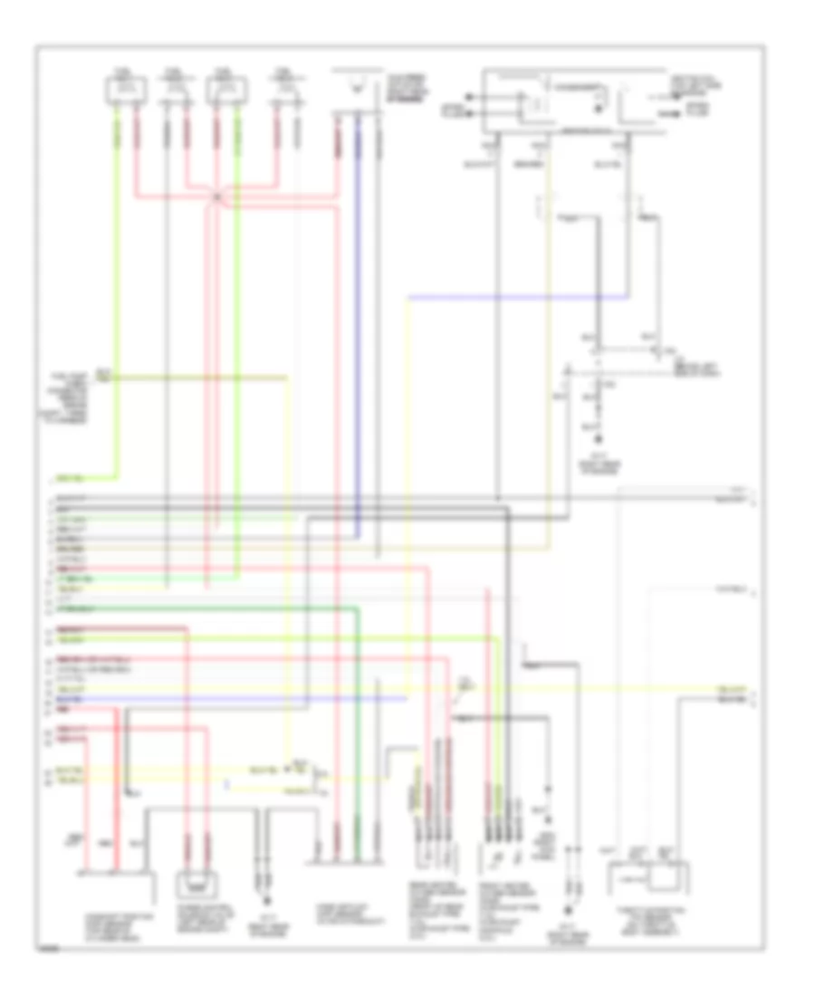
1.8L, Engine Performance Wiring Diagrams (1 of 3) for Hyundai Tiburon 1997

List of elements for 1.8L, Engine Performance Wiring Diagrams (1 of 3) for Hyundai Tiburon 1997:
- (1.8l)
- (2.0l)
- A/c relay cntrl a/c relay cntrl a/c relay cntrl a/c relay cntrl a/c relay cntrl a/c relay cntrl
- Acc
- Air conditioning system
- Audio fuse 10a
- Batt backup
- C31
- C32
- Can close valve cntrl
- Canister close valve (left front of engine compt, behind bumper)
- Cluster
- Cmp sensor input
- Cond fan rel cntrl
- Cooling fans system
- Crankshaft pos sens a
- Crankshaft pos sens b
- Crankshaft position (ckp) sensor (lower left side of engine)
- Dash fuse box (behind left side of dash, above kick panel)
- Ecm rel power input ecm rel power input ecm rel power input ecm rel power input ecm rel power input ecm rel power input
- Eng speed sig output
- Engine compartment fuse/relay box (left side of engine compt)
- Engine compartment fuse/relay box (left side of of engine compt)
- Engine control module (ecm) (behind left side of dash)
- Front ho2s htr cntrl front ho2s htr cntrl front ho2s htr cntrl front ho2s htr cntrl front ho2s htr cntrl front ho2s htr cntrl
- Front ho2s sensor
- Fuel inj 1 cntrl
- Fuel inj 2 cntrl fuel inj 2 cntrl fuel inj 2 cntrl fuel inj 2 cntrl fuel inj 2 cntrl fuel inj 2 cntrl
- Fuel inj 3 cntrl
- Fuel inj 4 cntrl
- Fuel pump motor (inside top of fuel tank)
- Fuel pump relay
- Fuel pump relay cntrl
- Fuse 10 10a
- G117 (right rear of engine)
- G904 (base of left "c" pillar)
- Ground
- Ground ground ground ground ground ground
- Hot at all times
- Hot at all times hot at all times hot at all times hot at all times hot at all times hot at all times
- I01-1
- I01-2
- Idle speed cntrl open
- Idle speed ctrl close
- Ig1
- Ign coil cntrl
- Ignition ignition ignition ignition ignition ignition switch switch switch switch switch switch
- Instrument
- Instrument cluster system
- J/c
- Lock
- Maf sensor ground
- Maf sensor input maf sensor input maf sensor input maf sensor input maf sensor input maf sensor input
- Malfunction indicator
- Mfi cntrl relay mfi cntrl relay mfi cntrl relay mfi cntrl relay mfi cntrl relay mfi cntrl relay
- Mil indicator
- Nca
- Passenger compartment relay box (behind left side of dash)
- Purge cntrl sol valve purge cntrl sol valve purge cntrl sol valve purge cntrl sol valve purge cntrl sol valve purge cntrl sol valve
- Radiator fan rel cntrl radiator fan rel cntrl radiator fan rel cntrl radiator fan rel cntrl radiator fan rel cntrl radiator fan rel cntrl
- Rear ho2s htr cntrl
- Rear ho2s sensor
- Rear ho2s sensor rear ho2s sensor rear ho2s sensor rear ho2s sensor rear ho2s sensor rear ho2s sensor
- Red
- Sfi control relay (behind left side of dash)
- Start
- Tp sensor output
- Transmission control module
- Vehicle speed input vehicle speed input vehicle speed input vehicle speed input vehicle speed input vehicle speed input
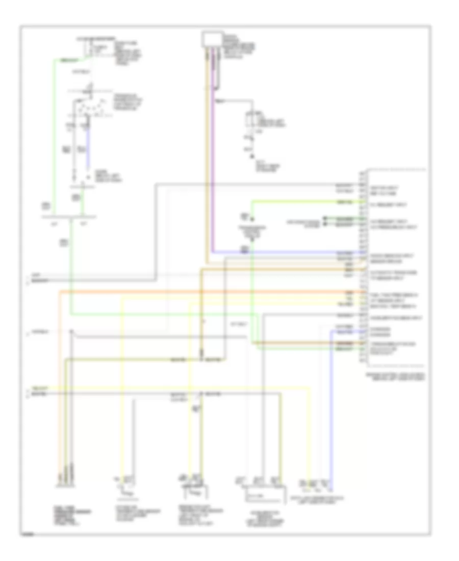
1.8L, Engine Performance Wiring Diagrams (2 of 3) for Hyundai Tiburon 1997
List of elements for 1.8L, Engine Performance Wiring Diagrams (2 of 3) for Hyundai Tiburon 1997:
- (right rear of engine)
- 1.8l
- 1.8l only
- 2.0l
- C32
- Camshaft position (cmp) sensor (top rear of cylinder head)
- Condenser
- Front heated oxygen sensor (ho2s) (in exhaust pipe) (1.8l) (in exhaust manifold) (2.0l)
- Fuel inj 1
- Fuel inj 2
- Fuel inj 3
- Fuel inj 4
- Fuel pump check connector (rear of engine compt, taped to harness)
- G117
- G203 (right kick panel)
- Idle speed actuator (right rear of engine) of engine) of engine)
- Ignition coil (top left side of engine)
- Ignition coils
- J/c (behind left side of dash)
- Mass air flow (maf) sensor (in air intake duct)
- Nca
- Purge control solenoid valve (left rear of engine compt)
- Rear heated oxygen sensor (ho2s) (front of rear exhaust pipe) (1.8l) (in exhaust pipe) (2.0l)
- Red
- Spark plugs
- Throttle position (tp) sensor (on throttle body assembly)
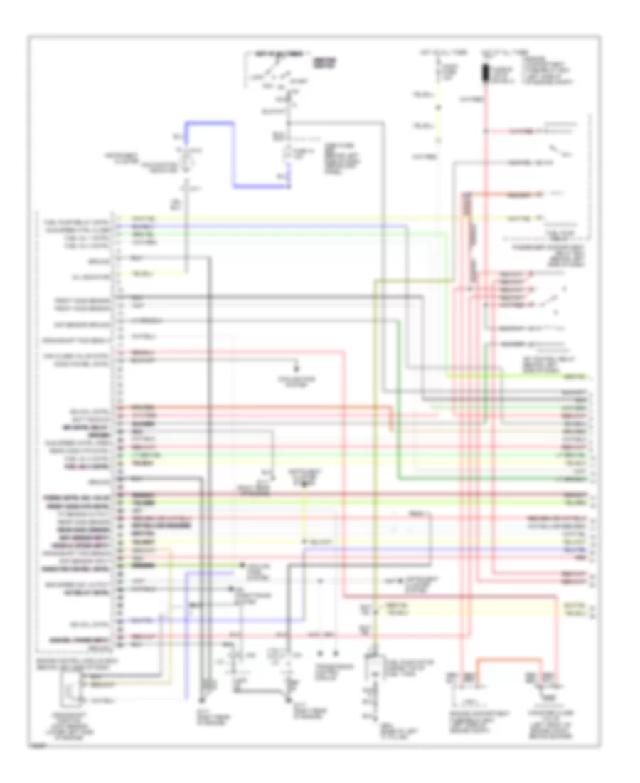
1.8L, Engine Performance Wiring Diagrams (3 of 3) for Hyundai Tiburon 1997
List of elements for 1.8L, Engine Performance Wiring Diagrams (3 of 3) for Hyundai Tiburon 1997:
- (left side of dash)
- A/c pressure sw input
- A/c request input
- A/t
- A/t only
- Acceleration sens input
- Acceleration sensor (left rear corner of engine compt)
- Air conditioning system
- Automatic trans mode
- C32
- Dash fuse box (behind left side of dash, above kick panel)
- Data link connector (dlc)
- Diagnosis
- Diode (below left side of dash)
- Eng cool temp sens in
- Engine control module (ecm) (behind left side of dash)
- Engine coolant temperature sensor (left front of engine, on coolant outlet)
- Fuel tank fuel tank pressure sensor pressure sensor (inside of (inside of left rear left rear wheel well)
- Fuel tank pres sens in
- Fuse 9 10a
- G117 (right rear of engine)
- Hot in on or start
- Iat sensor input
- Ignition input
- Intake air temperature sensor (in air cleaner housing)
- J/c (behind left side of dash)
- Knock sens sig input
- Knock sensor (lower center rear of engine, below intake manifold)
- M/t
- Mil request input
- Nca
- P/n in (a/t) or pwr in (m/t)
- Ref voltage
- Sensor ground
- Torque reduction sig
- Tp sensor input
- Transaxle range switch (top front of transaxle)
- Transmission control module
2.0L
2.0L, Engine Performance Wiring Diagrams (1 of 3) for Hyundai Tiburon 1997
List of elements for 2.0L, Engine Performance Wiring Diagrams (1 of 3) for Hyundai Tiburon 1997:
- (1.8l)
- (2.0l)
- A/c relay cntrl a/c relay cntrl a/c relay cntrl a/c relay cntrl a/c relay cntrl a/c relay cntrl
- Acc
- Air conditioning system
- Audio fuse 10a
- Batt backup
- C31
- C32
- Can close valve cntrl
- Canister close valve (left front of engine compt, behind bumper)
- Cluster
- Cmp sensor input
- Cond fan rel cntrl
- Cooling fans system
- Crankshaft pos sens a
- Crankshaft pos sens b
- Crankshaft position (ckp) sensor (lower left side of engine)
- Dash fuse box (behind left side of dash, above kick panel)
- Ecm rel power input ecm rel power input ecm rel power input ecm rel power input ecm rel power input ecm rel power input
- Eng speed sig output
- Engine compartment fuse/relay box (left side of engine compt)
- Engine compartment fuse/relay box (left side of of engine compt)
- Engine control module (ecm) (behind left side of dash)
- Front ho2s htr cntrl front ho2s htr cntrl front ho2s htr cntrl front ho2s htr cntrl front ho2s htr cntrl front ho2s htr cntrl
- Front ho2s sensor
- Fuel inj 1 cntrl
- Fuel inj 2 cntrl fuel inj 2 cntrl fuel inj 2 cntrl fuel inj 2 cntrl fuel inj 2 cntrl fuel inj 2 cntrl
- Fuel inj 3 cntrl
- Fuel inj 4 cntrl
- Fuel pump motor (inside top of fuel tank)
- Fuel pump relay
- Fuel pump relay cntrl
- Fuse 10 10a
- G117 (right rear of engine)
- G904 (base of left "c" pillar)
- Ground
- Ground ground ground ground ground ground
- Hot at all times
- Hot at all times hot at all times hot at all times hot at all times hot at all times hot at all times
- I01-1
- I01-2
- Idle speed cntrl open
- Idle speed ctrl close
- Ig1
- Ign coil cntrl
- Ignition ignition ignition ignition ignition ignition switch switch switch switch switch switch
- Instrument
- Instrument cluster system
- J/c
- Lock
- Maf sensor ground
- Maf sensor input maf sensor input maf sensor input maf sensor input maf sensor input maf sensor input
- Malfunction indicator
- Mfi cntrl relay mfi cntrl relay mfi cntrl relay mfi cntrl relay mfi cntrl relay mfi cntrl relay
- Mil indicator
- Nca
- Passenger compartment relay box (behind left side of dash)
- Purge cntrl sol valve purge cntrl sol valve purge cntrl sol valve purge cntrl sol valve purge cntrl sol valve purge cntrl sol valve
- Radiator fan rel cntrl radiator fan rel cntrl radiator fan rel cntrl radiator fan rel cntrl radiator fan rel cntrl radiator fan rel cntrl
- Rear ho2s htr cntrl
- Rear ho2s sensor
- Rear ho2s sensor rear ho2s sensor rear ho2s sensor rear ho2s sensor rear ho2s sensor rear ho2s sensor
- Red
- Sfi control relay (behind left side of dash)
- Start
- Tp sensor output
- Transmission control module
- Vehicle speed input vehicle speed input vehicle speed input vehicle speed input vehicle speed input vehicle speed input
2.0L, Engine Performance Wiring Diagrams (2 of 3) for Hyundai Tiburon 1997
List of elements for 2.0L, Engine Performance Wiring Diagrams (2 of 3) for Hyundai Tiburon 1997:
- (right rear of engine)
- 1.8l
- 1.8l only
- 2.0l
- C32
- Camshaft position (cmp) sensor (top rear of cylinder head)
- Condenser
- Front heated oxygen sensor (ho2s) (in exhaust pipe) (1.8l) (in exhaust manifold) (2.0l)
- Fuel inj 1
- Fuel inj 2
- Fuel inj 3
- Fuel inj 4
- Fuel pump check connector (rear of engine compt, taped to harness)
- G117
- G203 (right kick panel)
- Idle speed actuator (right rear of engine) of engine) of engine)
- Ignition coil (top left side of engine)
- Ignition coils
- J/c (behind left side of dash)
- Mass air flow (maf) sensor (in air intake duct)
- Nca
- Purge control solenoid valve (left rear of engine compt)
- Rear heated oxygen sensor (ho2s) (front of rear exhaust pipe) (1.8l) (in exhaust pipe) (2.0l)
- Red
- Spark plugs
- Throttle position (tp) sensor (on throttle body assembly)
2.0L, Engine Performance Wiring Diagrams (3 of 3) for Hyundai Tiburon 1997
List of elements for 2.0L, Engine Performance Wiring Diagrams (3 of 3) for Hyundai Tiburon 1997:
- (left side of dash)
- A/c pressure sw input
- A/c request input
- A/t
- A/t only
- Acceleration sens input
- Acceleration sensor (left rear corner of engine compt)
- Air conditioning system
- Automatic trans mode
- C32
- Dash fuse box (behind left side of dash, above kick panel)
- Data link connector (dlc)
- Diagnosis
- Diode (below left side of dash)
- Eng cool temp sens in
- Engine control module (ecm) (behind left side of dash)
- Engine coolant temperature sensor (left front of engine, on coolant outlet)
- Fuel tank fuel tank pressure sensor pressure sensor (inside of (inside of left rear left rear wheel well)
- Fuel tank pres sens in
- Fuse 9 10a
- G117 (right rear of engine)
- Hot in on or start
- Iat sensor input
- Ignition input
- Intake air temperature sensor (in air cleaner housing)
- J/c (behind left side of dash)
- Knock sens sig input
- Knock sensor (lower center rear of engine, below intake manifold)
- M/t
- Mil request input
- Nca
- P/n in (a/t) or pwr in (m/t)
- Ref voltage
- Sensor ground
- Torque reduction sig
- Tp sensor input
- Transaxle range switch (top front of transaxle)
- Transmission control module