ENGINE PERFORMANCE
3.5L
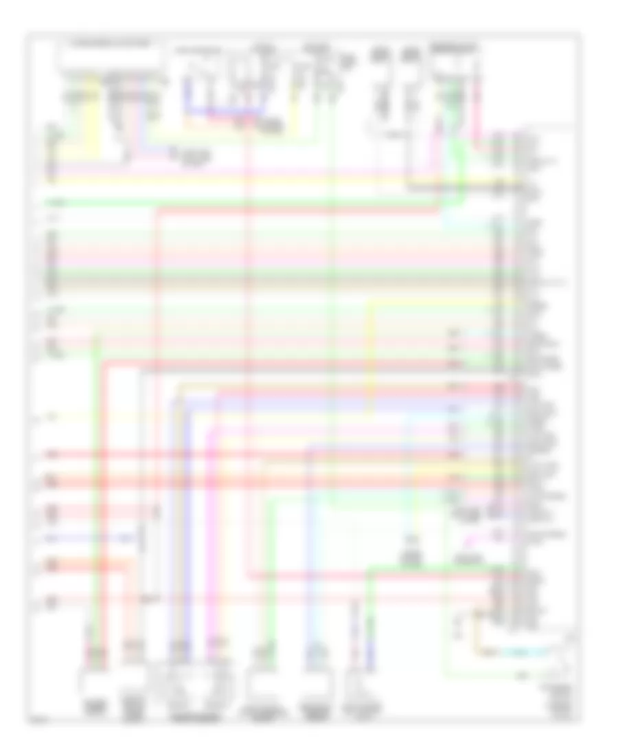
3.5L, Engine Performance Wiring Diagram (1 of 4) for Infiniti EX35 2008

List of elements for 3.5L, Engine Performance Wiring Diagram (1 of 4) for Infiniti EX35 2008:
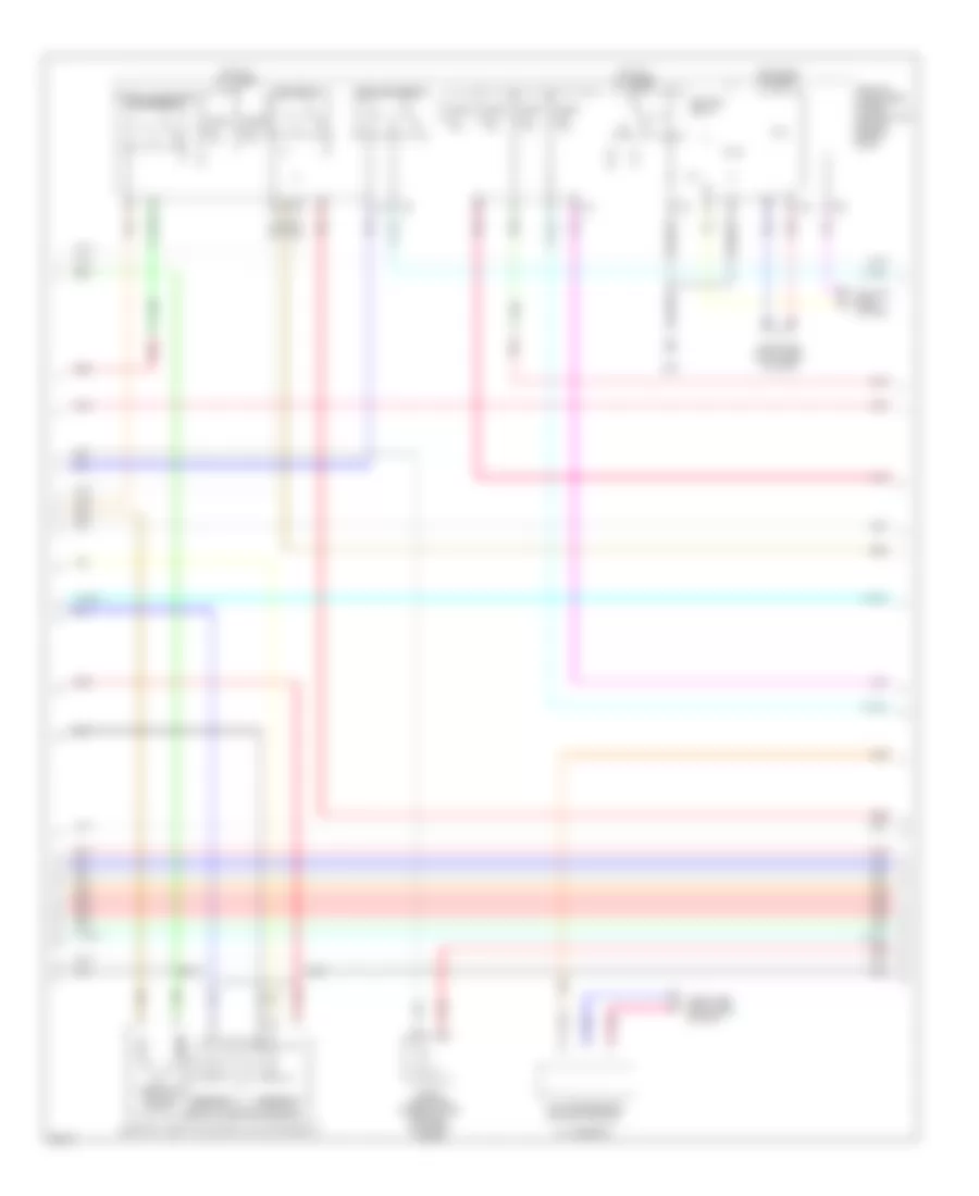
3.5L, Engine Performance Wiring Diagram (2 of 4) for Infiniti EX35 2008
List of elements for 3.5L, Engine Performance Wiring Diagram (2 of 4) for Infiniti EX35 2008:
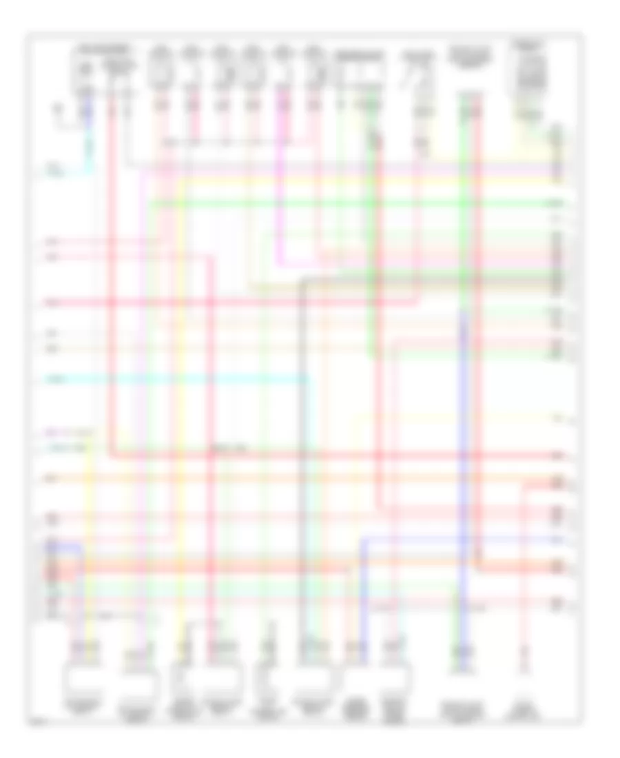
3.5L, Engine Performance Wiring Diagram (3 of 4) for Infiniti EX35 2008
List of elements for 3.5L, Engine Performance Wiring Diagram (3 of 4) for Infiniti EX35 2008:
3.5L, Engine Performance Wiring Diagram (4 of 4) for Infiniti EX35 2008
List of elements for 3.5L, Engine Performance Wiring Diagram (4 of 4) for Infiniti EX35 2008: