ENGINE PERFORMANCE
4.5L
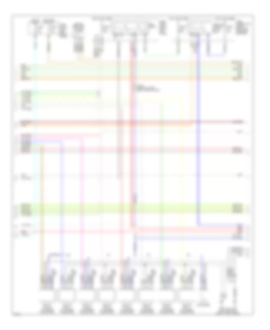
4.5L, Engine Performance Wiring Diagram (1 of 5) for Infiniti Q45 2004

List of elements for 4.5L, Engine Performance Wiring Diagram (1 of 5) for Infiniti Q45 2004:
- (behind right kick panel)
- (behind upper left side of dash) j/c 4
- A/c system
- Acrly
- Active damper suspension unit control unit (left rear shock tower)
- Ascd control unit (behind dash, left of steering column)
- Combination meter
- Cooling fan speed control solenoid valve (on front of engine)
- Crankshaft position sensor (pos) (on rear of cyl block)
- Crtn
- Cvbv
- Dual mode muffler control unit (at right of trunk)
- Engine control module (ecm) (behind glove box)
- Etc prun
- Evap
- Evap canister purge volume control solenoid valve (on top right rear of engine)
- F8 (left front of eng comp, near eng oil level gauge)
- Fpcm
- Fpr
- Fuel injector
- Fuse 10a
- Fuse block (j/b) 1 (left end of panel)
- Hot in on or start
- Ign 1
- Ign 2
- Ign 3
- Ign 4
- Ign 5
- Ign 6
- Ign 7
- Ign 8
- Ignsw
- Inj 1
- Inj 2
- Inj 3
- Inj 4
- Inj 5
- Inj 6
- Inj 7
- Inj 8
- J/c (behind right kick panel)
- J/c 19 (behind right end of dash)
- J/c 28
- Led
- Malfunction indicator lamp
- Motrly
- Nca
- O2hfl
- O2hfr
- O2hrl
- O2hrr
- Pnk
- Pos
- Power steering control unit (behind dash, right side of center console)
- Prf+
- Prf-
- Prun in
- Red
- Ssoff
- Stsw
- Tacho
- Tp in
- Tvo0
- Unified meter control unit
- Vacuum cut valve bypass valve (under rear of vehicle, forward of evap canister)
- Vias
- Vias control solenoid valve (top front center of engine)
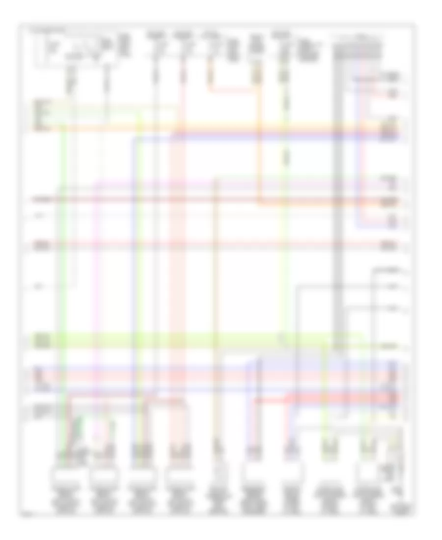
4.5L, Engine Performance Wiring Diagram (2 of 5) for Infiniti Q45 2004
List of elements for 4.5L, Engine Performance Wiring Diagram (2 of 5) for Infiniti Q45 2004:
- (behind right end of dash) j/c 19
- (left front of eng comp, near eng oil level gauge)
- 22r
- Condenser
- Ecm relay
- Fuse 10a
- Fuse 15a
- Fuse 20a
- Fuse block (j/b) 1 (left end of panel)
- Fuse block (j/b) 2 (right kick panel)
- Fuse, fusible link & relay block (j/b) (in engine room box)
- Hot at all times
- Hot in on or start
- Hot in start
- Ignition coil 1 (w/ power transistor)
- Ignition coil 2 (w/ power transistor)
- Ignition coil 3 (w/ power transistor)
- Ignition coil 4 (w/ power transistor)
- Ignition coil 5 (w/ power transistor)
- Ignition coil 6 (w/ power transistor)
- Ignition coil 7 (w/ power transistor)
- Ignition coil 8 (w/ power transistor)
- J/c 21 (behind lower right side of dash)
- Nca
- Plug spark
- Red
- Spark plug
- Throttle control motor relay
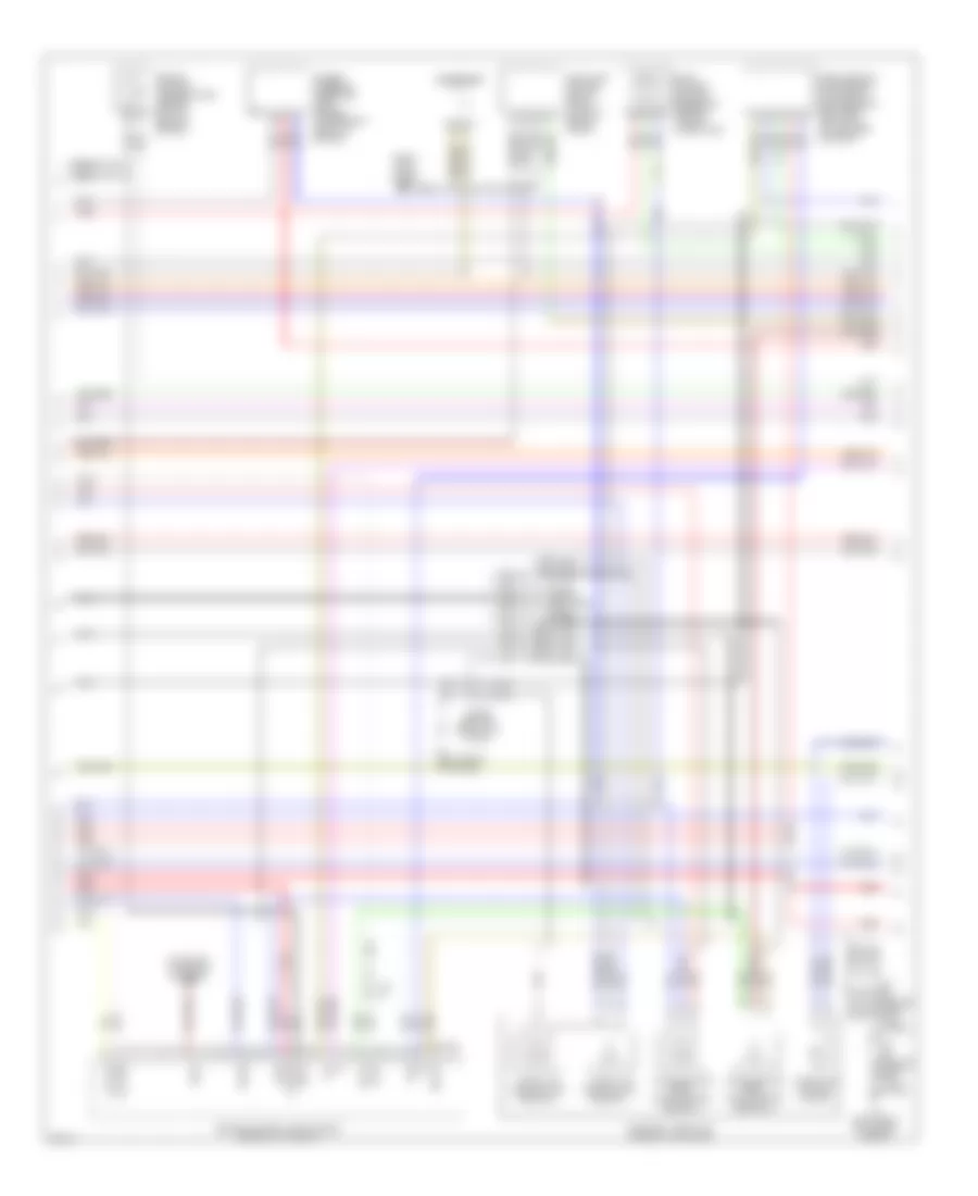
4.5L, Engine Performance Wiring Diagram (3 of 5) for Infiniti Q45 2004
List of elements for 4.5L, Engine Performance Wiring Diagram (3 of 5) for Infiniti Q45 2004:
- (behind top center of dash) j/c 12
- 33r
- 34r
- Camshaft position sensor (phase) (on front of left cyl head)
- F8 (left front of engine compt)
- Fuel pump relay
- Fuse 10a
- Fuse 15a
- Fuse block (j/b) 1 (left end of dash)
- Fuse block (j/b) 2 (right kick panel)
- Fuse, fusible link & relay block (j/b) (in engine room box)
- Heated oxygen sensor 1 (bank 1) (on inlet of left manifold three-way catalyst)
- Heated oxygen sensor 1 (bank 2) (on inlet of right manifold three-way catalyst)
- Heated oxygen sensor 2 (bank 1) (on outlet of left manifold three-way catalyst)
- Heated oxygen sensor 2 (bank 2) (on outlet of right manifold three-way catalyst)
- Hot at all times
- Hot in on or start
- Intake valve timing control position sensor (bank 1) (on front of left cyl head)
- Intake valve timing control position sensor (bank 2) (on front of right cyl head)
- J/c 29 (behind right kick panel)
- J/c 30
- Nca
- Panel)
- Radiator coolant temperature sensor (left side of radiator)
- Red
- Refrigerant pressure sensor (front right side of engine compt, near condenser)
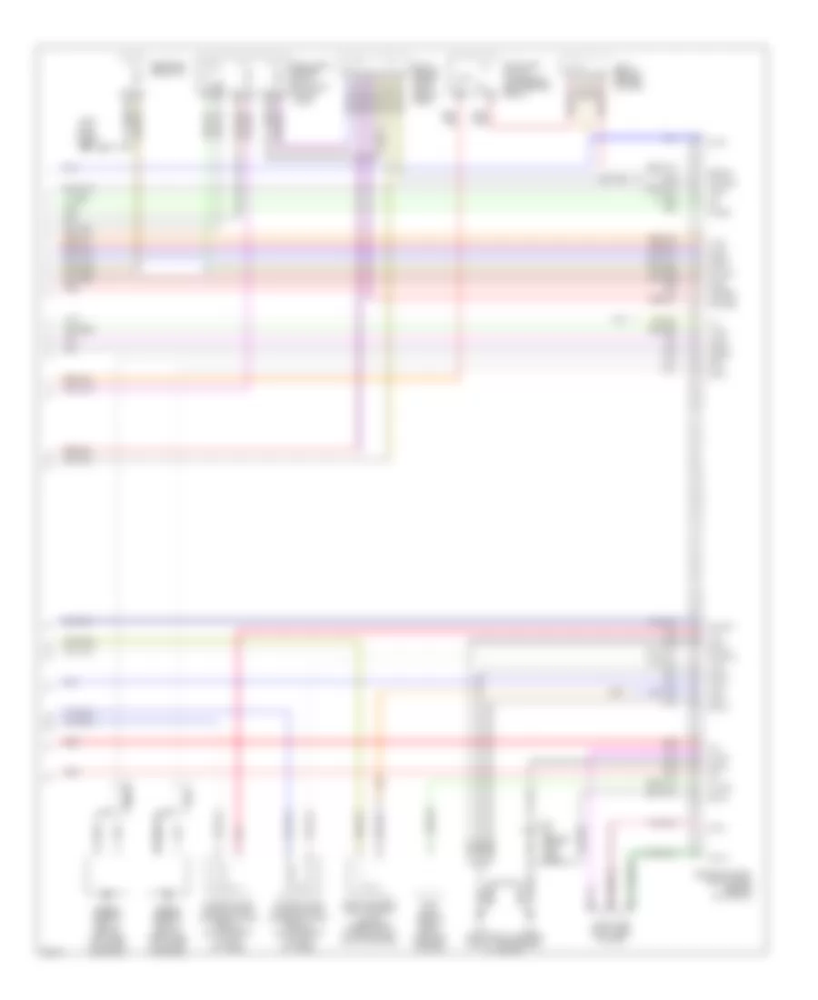
4.5L, Engine Performance Wiring Diagram (4 of 5) for Infiniti Q45 2004
List of elements for 4.5L, Engine Performance Wiring Diagram (4 of 5) for Infiniti Q45 2004:
- (right kick panel) b217
- Accelerator pedal position (app) sensor 1
- Accelerator pedal position (app) sensor 2
- Aps1
- Avcc2
- Batt
- Condenser
- Electric throttle control actuator
- Engine control module (ecm) (behind glove box)
- Engine coolant temperature sensor (on top rear of engine)
- Evap control system pressure sensor (in evap purge line)
- F8 (left front of engine compt)
- F8 (left front of engine)
- Fuel pump control module (fpcm) (on right side of trunk)
- Gnd a
- Gnd a2
- Ivcpusl
- Ivcpusr
- J/c
- J/c (behind right kick panel)
- J/c 28 (behind right kick panel)
- J/c 29 (behind right kick panel)
- Mass airflow (maf) sensor (intake air temp sensor) (between air duct & air cleaner housing)
- Nca
- Neut
- Pdpres
- Phase
- Pnk
- Power steering pressure (psp) sensor (lower right front of engine)
- Qa+
- Red
- Starting/ charging system
- Throttle control motor
- Throttle position (tp) sensor 1
- Throttle position (tp) sensor 2
- Tps2
4.5L, Engine Performance Wiring Diagram (5 of 5) for Infiniti Q45 2004
List of elements for 4.5L, Engine Performance Wiring Diagram (5 of 5) for Infiniti Q45 2004:
- (left front of engine compt, near engine oil gauge)
- (left kick panel) b17
- Aps2
- Avcc
- Brksw
- Can h
- Can l
- Cdcv
- Computer data lines system
- Dropping resistor
- Engine control module (ecm) (behind glove box)
- Evap canister vent control valve (under rear of vehicle, on evap canister)
- Fgauge+
- Fgauge-
- Fpcmck
- Ftprs
- Fuel level sensor unit & fuel pump (in fuel tank)
- Gnd c
- Gnd e
- Gnd m
- Im lime
- Intake valve timing control solenoid valve (bank 1) (on top front of left cyl head)
- Intake valve timing control solenoid valve (bank 2) (on top front of right cyl head)
- Ivcl
- Ivcr
- J/c (behind right kick panel)
- J/c 15 (behind upper right side of dash)
- J/c 7 (behind center of dash)
- Kline
- Knk1
- Knk2
- Knock sensor (bank 1) (below left side of intake manifold)
- Knock sensor (bank 2) (below right side of intake manifold)
- Motor 1
- Motor 2
- Nats immu (behind dash, left of steering column)
- Nca
- O2sfl
- O2sfr
- O2srl
- O2srr
- Pnk
- Pspres
- Qa-
- Red
- Stop lamp switch (on bracket, above brake pedal)
- Tps1
- Tvo0
- Twrf
- Vmot