ENGINE PERFORMANCE
3.2L
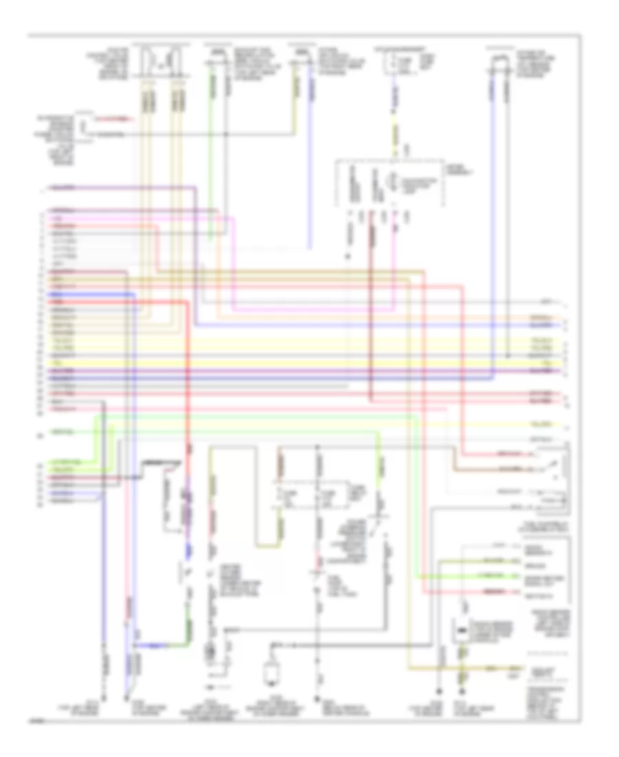
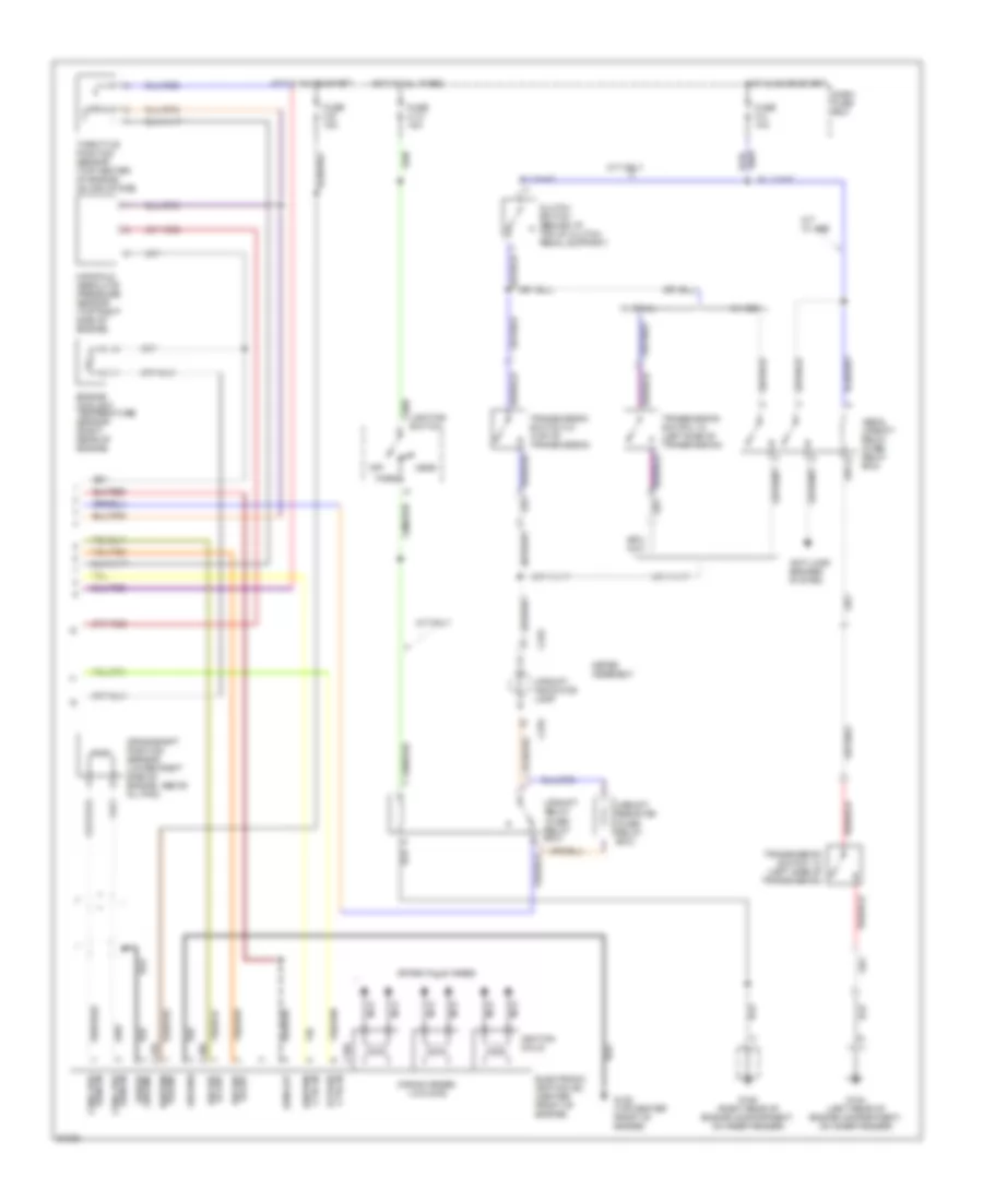
3.2L DOHC, Engine Performance Wiring Diagrams (1 of 3) for Isuzu Trooper S 1994

List of elements for 3.2L DOHC, Engine Performance Wiring Diagrams (1 of 3) for Isuzu Trooper S 1994:
- (a/t)
- (m/t)
- 5v reference
- A/c on in
- A/c relay ctrl
- A10
- A11
- A12
- Air conditioning system (a/c control relay)
- Air conditioning system (a/c thermostat relay)
- B10
- B11
- B12
- Battery input
- Bypass control
- C10
- C11
- C12
- C13
- C14
- C15
- C16
- C200
- C201
- Canister vac vlve ctrl
- Coolant temp out
- D10
- D11
- D12
- D13
- D14
- D15
- D16
- Dash fuse box
- Data link connector (below left center of i/p)
- Diagnostic input
- Ecm main relay (fuse/ relay box)
- Egr vac valve ctrl
- Engine control module (behind front of center console)
- Engine coolant temp in
- External resistor
- Fl3 (ecm) fuse 30a
- Fuel injector ctrl
- Fuel injectors (top of engine)
- Fuel pump relay ctrl
- Fuse c-8 15a
- Fuse/ relay box
- G105 (right side of engine compart- ment on inner fender panel)
- Ground
- Hot at all times
- Hot in on or start
- Iac valve ctrl
- Ignition control out
- Ignition in
- Ignition ref hi
- Ignition ref lo
- Intake air temp in
- Intake air valve ctrl
- Map sensor in
- Mil indicator ctrl
- Not used
- Oxygen sensor hi
- Oxygen sensor lo
- Park/neutral in
- Pwr steering press in
- Red
- Sensor ground
- Serial data
- Spark retard in
- Starting/charging system (a/t only) (diode box a)
- Tps sensor in
- Upshift indicator ctrl
- Vss in
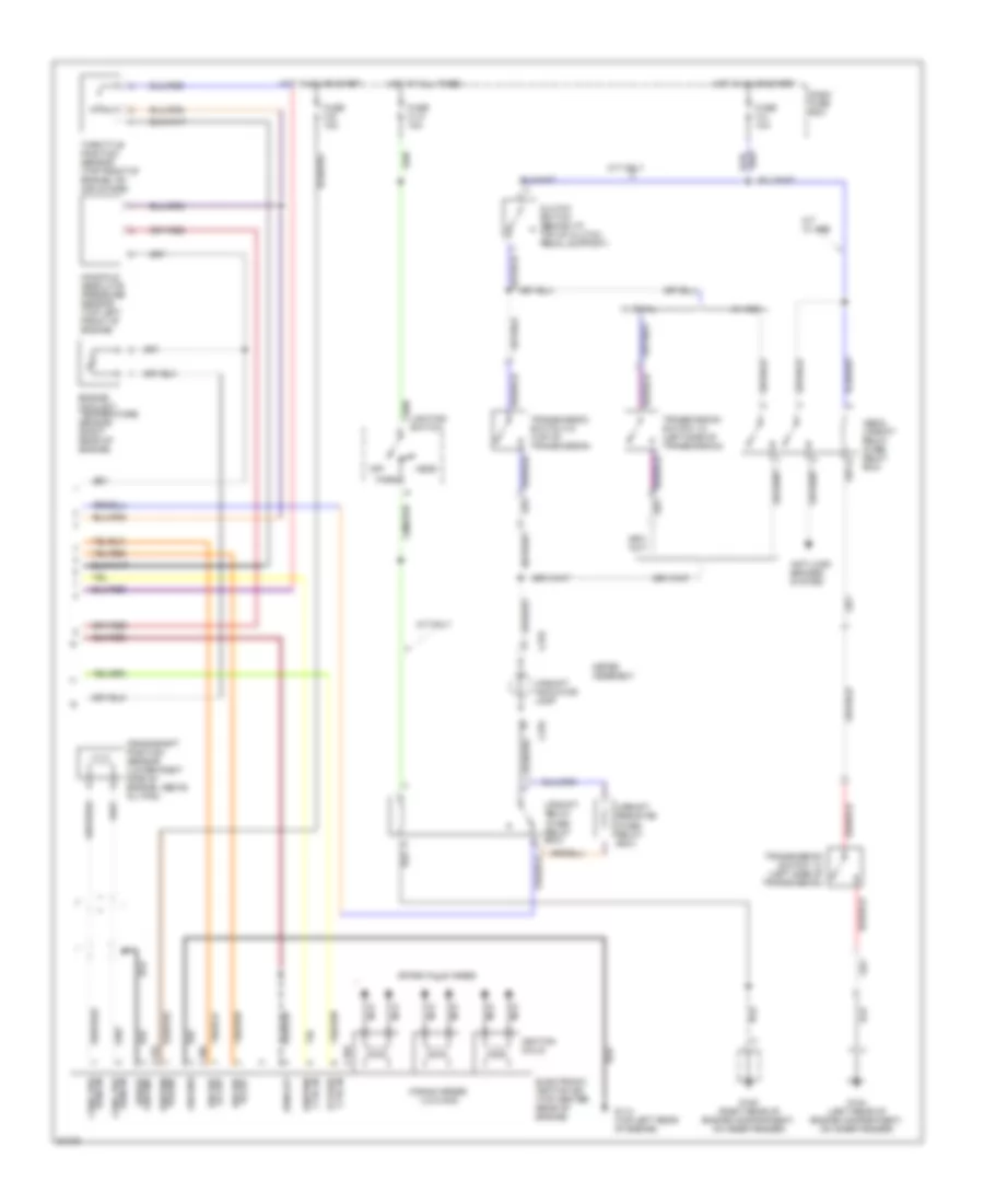
3.2L DOHC, Engine Performance Wiring Diagrams (2 of 3) for Isuzu Trooper S 1994
List of elements for 3.2L DOHC, Engine Performance Wiring Diagrams (2 of 3) for Isuzu Trooper S 1994:
- (a/t)
- (m/t)
- Braid
- C207
- C278
- C279
- Coolant temp in
- D14
- Dash/ fuse box
- Evaporative emission canister purge vacuum switching valve (top left front of engine)
- Exhaust gas recirculation (egr) vacuum switching valve (top left rear of engine)
- Fuel pump (top of fuel tank)
- Fuel pump relay (in fuse/relay box)
- Fuse c-10 7.5a
- Fuse f-10 15a
- Fuse f-2 10a
- Fuse/ relay box
- G104 (left rear of engine compartment, on inner fender)
- G105 (right rear of engine compartment, on inner fender)
- G114 (top left rear of engine)
- G125 (top center of engine)
- G302 (below rear of center console)
- Ground
- Heated oxygen sensor (under center of vehicle, in exhaust pipe)
- Hot in on or start
- Idle air control valve (top center front of engine, on air intake)
- Ignition in
- Intake air temperature (iat) sensor (top center of engine)
- Intake air vacuum switching valve (top right rear of engine)
- Knock sensor (top of engine, under intake manifold)
- Knock sensor controller (left side of engine comp- artment)
- Knock sensor in
- Malfunction indicator lamp
- Meter assembly
- Output speedometer
- Power steering pressure switch (lower right front of engine compartment)
- Red
- Spark retard signal out
- Tachometer input
- Transmission control module (tcm) (behind i/p, top of left kick panel)
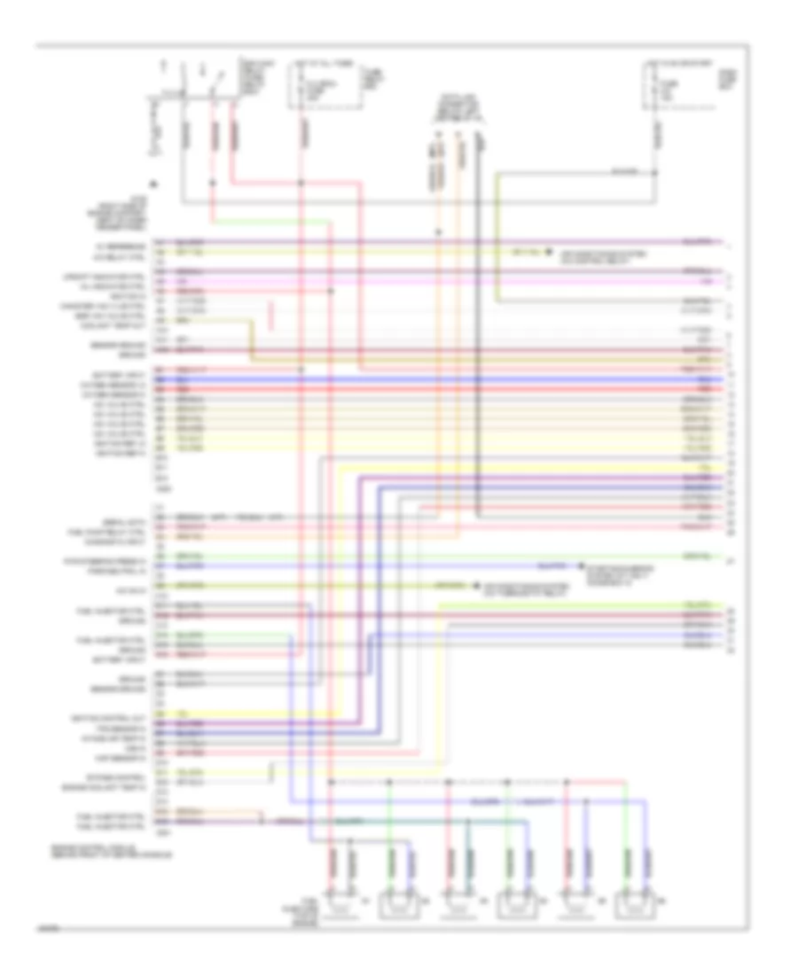
3.2L DOHC, Engine Performance Wiring Diagrams (3 of 3) for Isuzu Trooper S 1994
List of elements for 3.2L DOHC, Engine Performance Wiring Diagrams (3 of 3) for Isuzu Trooper S 1994:
- (firing order: 1-2-3-4-5-6)
- (fuse/ relay box)
- Abs & upshift relay (fuse/ relay box)
- Anti-lock brakes system
- C169
- C170
- C186
- C278
- Clutch switch (behind i/p, top of clutch pedal support)
- Crankshaft position sensor (lower right side of engine, above oil pan)
- Crnk pos sens in
- Ctrl in bypass
- Ctrl in ignition
- Dash fuse box
- Electronic ignition (ei) (top center rear of engine)
- Engine coolant temperature sensor (right rear of engine)
- Fuse c-13 15a
- Fuse c-4 10a
- Fuse c-9 15a
- G104 (left rear of engine compartment, on inner fender)
- G105 (right rear of engine compartment, on inner fender)
- G114 (top left rear of engine)
- Ground
- Head
- Hi out ign ref
- Hot at all times
- Hot in on or start
- Ignition coils
- Lighting switch
- Lo out ign ref
- M/t only
- M/t w/ abs
- Manifold absolute pressure sensor (top left front of engine)
- Meter assembly
- Nca
- Off
- Park
- Power ignition
- Rpm out
- Sens in crnk pos
- Shield ground
- Spark plug wires
- Throttle position sensor (top front of engine, on air intake)
- Transmission switch 1-2 (left side of transmission)
- Transmission switch 3-4 (top of transmission)
- Upshift indicator lamp
- Upshift relay
- Upshift resistor
- W/ abs
- W/ rwal
3.2L SOHC, Engine Performance Wiring Diagrams (1 of 3) for Isuzu Trooper S 1994
List of elements for 3.2L SOHC, Engine Performance Wiring Diagrams (1 of 3) for Isuzu Trooper S 1994:
- (a/t)
- (m/t)
- 5v reference
- A/c on in
- A/c relay ctrl
- A10
- A11
- A12
- Air conditioning system (a/c control relay)
- Air conditioning system (a/c thermostat relay)
- B10
- B11
- B12
- Battery input
- Bypass control
- C10
- C11
- C12
- C13
- C14
- C15
- C16
- C200
- C201
- Canister vac vlve ctrl
- Coolant temp out
- D10
- D11
- D12
- D13
- D14
- D15
- D16
- Dash fuse box
- Data link connector (below left center of i/p)
- Diagnostic input
- Ecm main relay (fuse/ relay box)
- Egr vac valve ctrl
- Engine control module (behind front of center console)
- Engine coolant temp in
- Fl3 (ecm) fuse 30a
- Fuel injector ctrl
- Fuel injectors (top of engine)
- Fuel pump relay ctrl
- Fuse c-8 15a
- Fuse/ relay box
- G105 (right side of engine compart- ment on inner fender panel)
- Ground
- Hot at all times
- Hot in on or start
- Iac valve ctrl
- Ignition control out
- Ignition in
- Ignition ref hi
- Ignition ref lo
- Intake air temp in
- Map sensor in
- Mil indicator ctrl
- Oxygen sensor hi
- Oxygen sensor lo
- Park/neutral in
- Pwr steering press in
- Red
- Sensor ground
- Serial data
- Starting/charging system (a/t only) (diode box a)
- Tps sensor in
- Upshift indicator ctrl
- Vss in
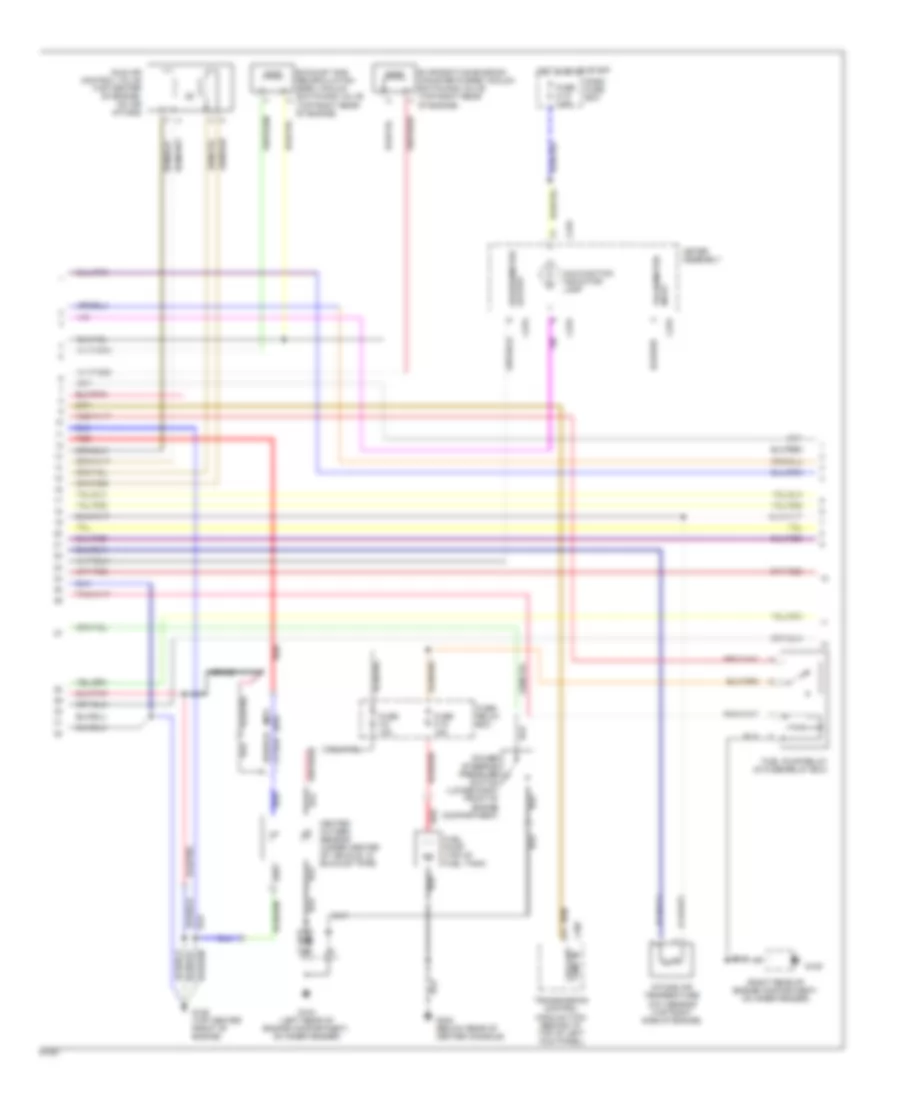
3.2L SOHC, Engine Performance Wiring Diagrams (2 of 3) for Isuzu Trooper S 1994
List of elements for 3.2L SOHC, Engine Performance Wiring Diagrams (2 of 3) for Isuzu Trooper S 1994:
- (a/t)
- (m/t)
- (right rear of engine compartment, on inner fender)
- Braid
- C207
- C278
- C279
- Coolant temp in
- D14
- Dash fuse box
- Evaporative emission canister purge vacuum switching valve (top right rear of engine)
- Exhaust gas recirculation (egr) vacuum switching valve (top right rear of engine)
- Fuel pump (top of fuel tank)
- Fuel pump relay (in fuse/relay box)
- Fuse c-10 7.5a
- Fuse f-10 15a
- Fuse f-2 10a
- Fuse/ relay box
- G104 (left rear of engine compartment, on inner fender)
- G105
- G125 (top center front of engine)
- G302 (below rear of center console)
- Heated oxygen sensor (under center of vehicle, in exhaust pipe)
- Hot in on or start
- Idle air control valve (top center of engine, on air intake)
- Intake air temperature (iat) sensor (top right side of engine)
- Malfunction indicator lamp
- Meter assembly
- Output speedometer
- Power steering pressure switch (lower right front of engine compartment)
- Red
- Tachometer input
- Transmission control module (tcm) (behind i/p, top of left kick panel)
3.2L SOHC, Engine Performance Wiring Diagrams (3 of 3) for Isuzu Trooper S 1994
List of elements for 3.2L SOHC, Engine Performance Wiring Diagrams (3 of 3) for Isuzu Trooper S 1994:
- (firing order: 1-2-3-4-5-6)
- (fuse/ relay box)
- Abs & upshift relay (fuse/ relay box)
- Anti-lock brakes system
- C169
- C170
- C186
- C278
- Clutch switch (behind i/p, top of clutch pedal support)
- Crankshaft position sensor (lower right side of engine, above oil pan)
- Crnk pos sens in
- Ctrl in bypass
- Ctrl in ignition
- Dash fuse box
- Electronic ignition (ei) (center front of engine)
- Engine coolant temperature sensor (right rear of engine)
- Fuse c-13 15a
- Fuse c-4 10a
- Fuse c-9 15a
- G104 (left rear of engine compartment, on inner fender)
- G105 (right rear of engine compartment, on inner fender)
- G125 (top center front of engine)
- Ground
- Head
- Hi out ign ref
- Hot at all times
- Hot in on or start
- Ignition coils
- Lighting switch
- Lo out ign ref
- M/t only
- M/t w/ abs
- Manifold absolute pressure sensor (top right side of engine)
- Meter assembly
- Nca
- Off
- Park
- Power ignition
- Rpm out
- Sens in crnk pos
- Shield ground
- Spark plug wires
- Throttle position sensor (top center of engine, on air intake)
- Transmission switch 1-2 (left side of transmission)
- Transmission switch 3-4 (top of transmission)
- Upshift indicator lamp
- Upshift relay
- Upshift resistor
- W/ abs
- W/ rwal