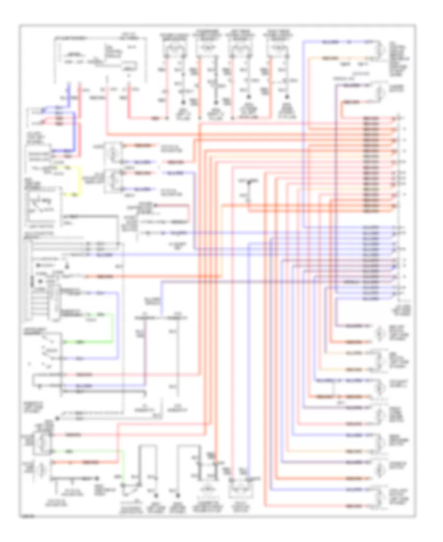
HORN
Horn Wiring Diagram for Hyundai Sonata GLS 2010
List of elements for Horn Wiring Diagram for Hyundai Sonata GLS 2010:
- (not used)
- 4wd lock switch (left side of dash)
- A/c control module (behind center of dash, forward of shift lever)
- A/v & navigation head unit
- Atm shift lever ill
- Audio
- Auto
- Auto a/c
- Aux & usb jack
- B-can
- B-can high
- B-can low
- Bcm (center of dash)
- Cigarette lighter & front power outlet
- Console switch
- Dbc switch (left side of dash)
- Down
- Esc off switch (left side of dash)
- Fd11
- Fd31
- Fd41
- Front wiper deicer switch
- Gf01 (left "a" pillar)
- Gf02 (at base of left "b" pillar)
- Gf06 (right "a" pillar)
- Gf08 (base of right "c" pillar)
- Glove box lamp
- Glove box lamp switch
- Gm01 (left side of dash)
- Gm02 (center of dash)
- Gm03 (center of dash)
- Hazard switch
- Head
- High
- Hot at all times
- I/p junction box
- I/p-d
- I/p-f
- I/p-h
- Ill (+)
- Ill (-)
- Ill control
- Instrument cluster
- Ips 3
- Ips control module
- J/c jm01 (top left of dash)
- J/c jm02 (left side of dash)
- Left rear power window switch
- Light switch
- Low
- M13-b
- M15-a
- M20-l
- M20-r
- M40
- M41-a
- M43-b
- M45-a
- M50-a
- Manual a/c
- Mf11
- Micom
- Multi- function switch
- Multi-function switch
- Nca
- Off
- Passenger power window switch
- Power distribution system
- Power window main switch
- Rear defogger switch
- Red
- Rheostat (left side of dash)
- Rheostat down sw
- Rheostat up sw
- Right rear power window switch
- S gnd
- Start stop button switch
- Tail
- Tail lamp sw m13-a
- Vcc
- W/ a/v & navigation
- W/ rheostat
- W/ smart key
- W/o a/v & navigation
- W/o rheostat
 English