
HORN
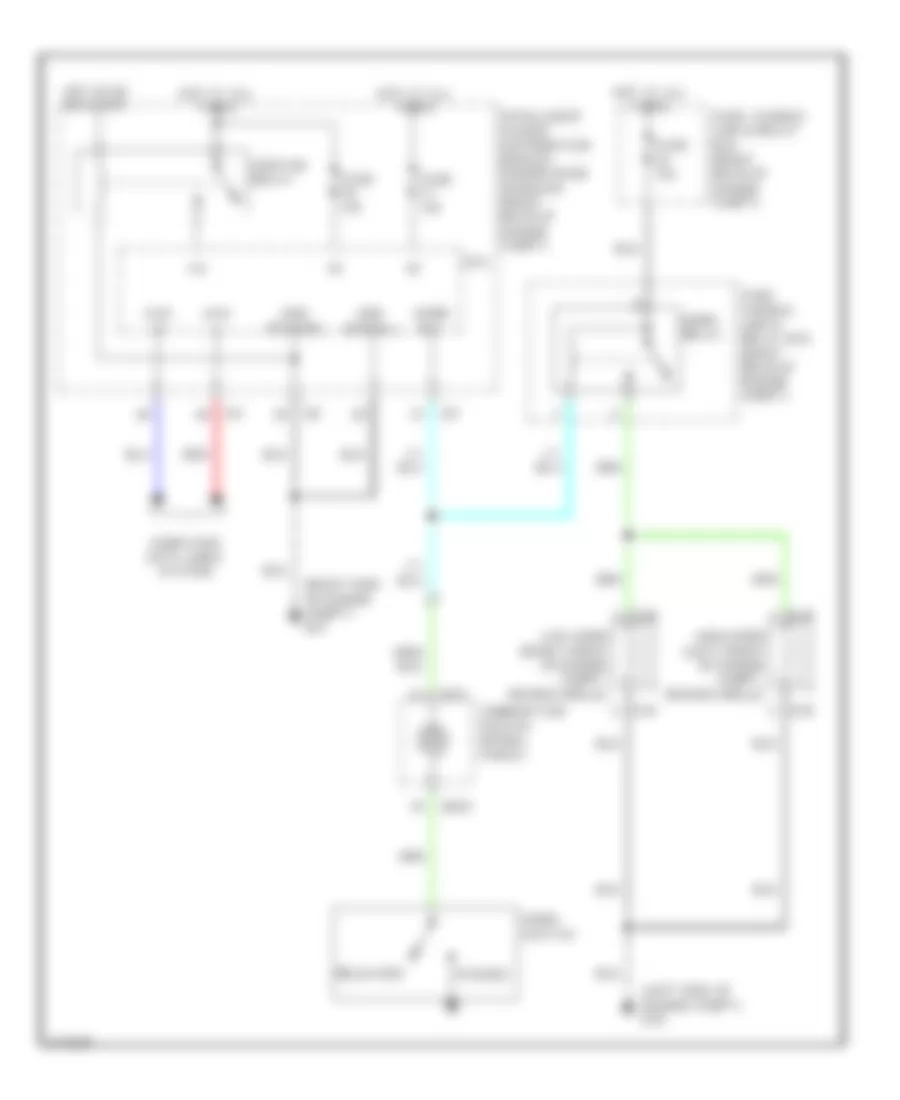
Horn Wiring Diagram for Infiniti FX35 2006
List of elements for Horn Wiring Diagram for Infiniti FX35 2006:
ANTI-LOCK BRAKESBODY CONTROL MODULESDEFOGGERSANTI-THEFTCOOLING FANAIR CONDITIONINGCOMPUTER DATA LINESCRUISE CONTROLENGINE PERFORMANCEEXTERIOR LIGHTSHEADLIGHTSINTERIOR LIGHTSMEMORY SYSTEMSHORNNAVIGATIONGROUND DISTRIBUTIONPOWER DOOR LOCKSPOWER SEATSPOWER MIRRORSPOWER DISTRIBUTIONINSTRUMENT CLUSTERPOWER WINDOWSPOWER TOP/SUNROOFTRUNK, TAILGATE, FUEL DOORSHIFT INTERLOCKTRANSMISSIONSTARTING/CHARGINGRADIOSUPPLEMENTAL RESTRAINTSWARNING SYSTEMSWIPER/WASHER