POWER DISTRIBUTION
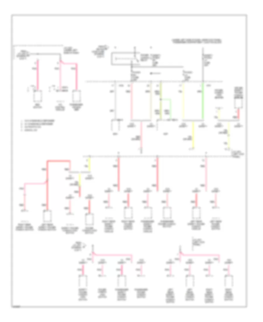
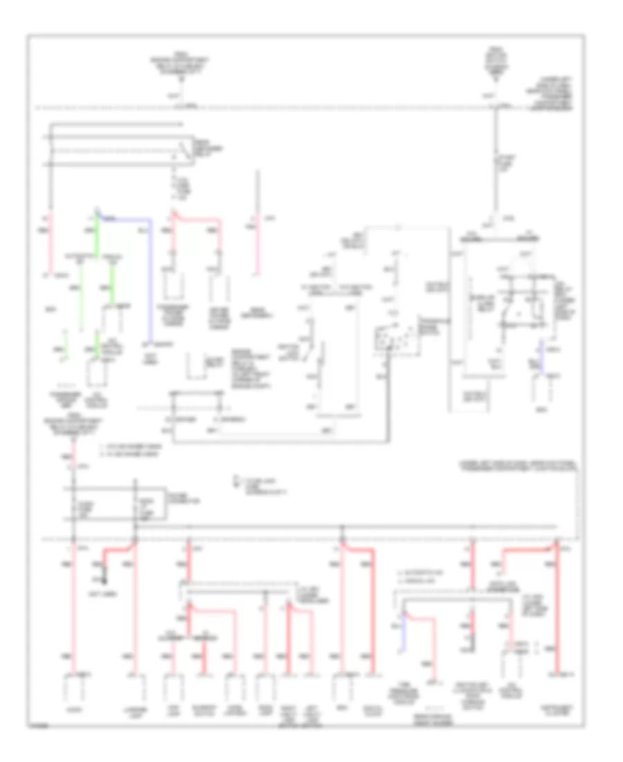
Power Distribution Wiring Diagram (1 of 7) for Hyundai Elantra Touring GLS 2010

List of elements for Power Distribution Wiring Diagram (1 of 7) for Hyundai Elantra Touring GLS 2010:
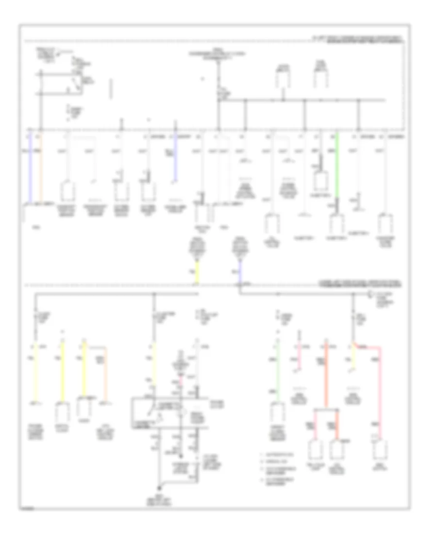
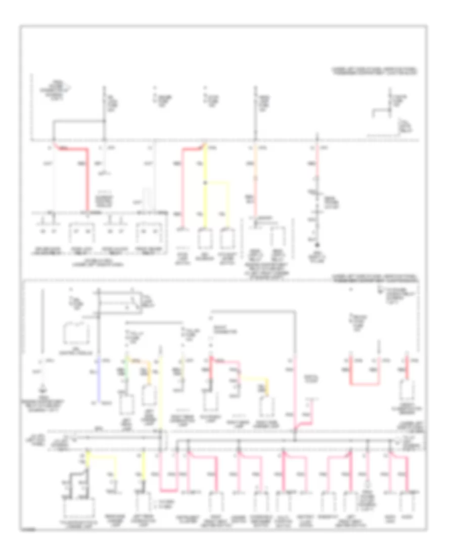
Power Distribution Wiring Diagram (2 of 7) for Hyundai Elantra Touring GLS 2010
List of elements for Power Distribution Wiring Diagram (2 of 7) for Hyundai Elantra Touring GLS 2010:
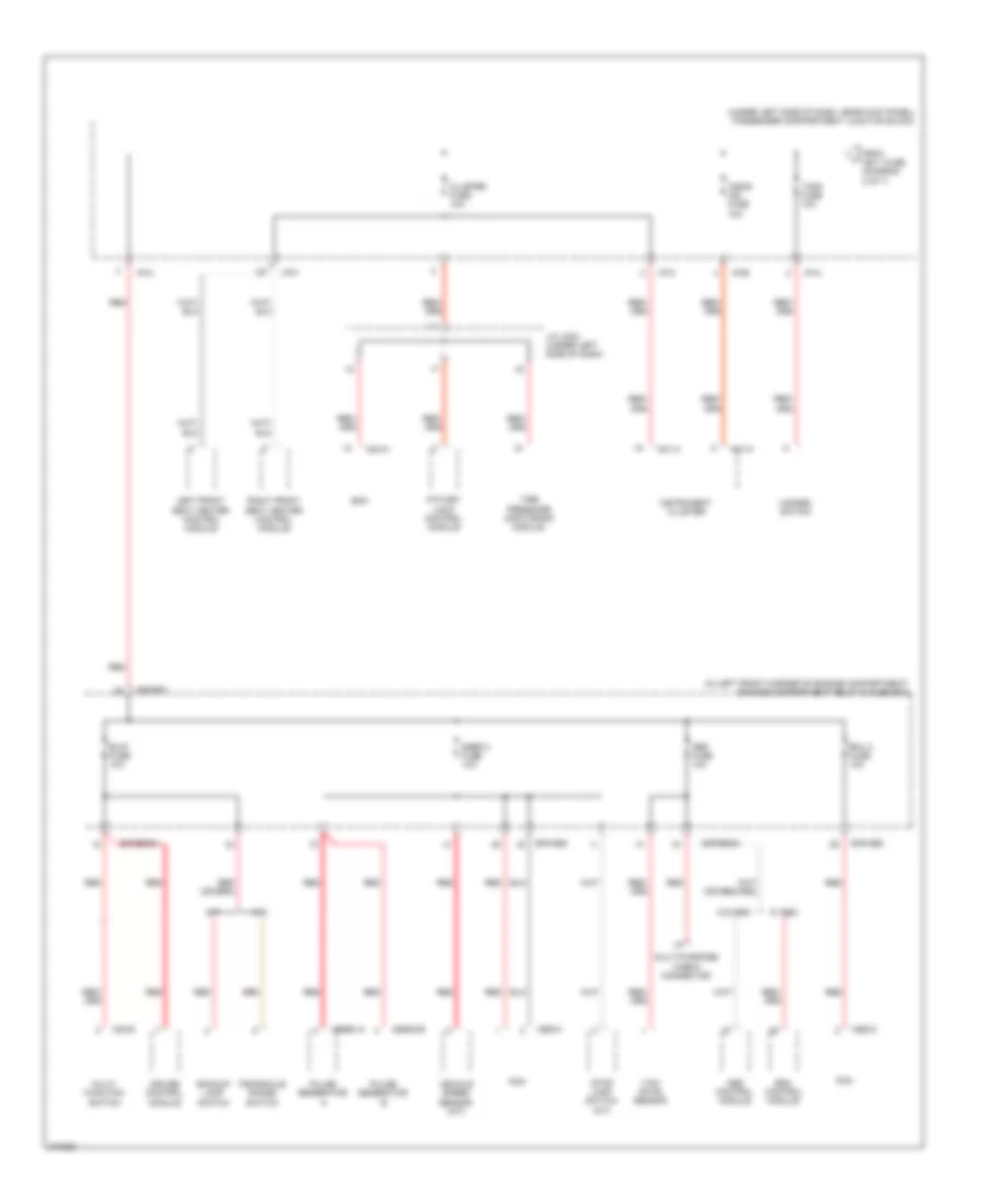
Power Distribution Wiring Diagram (3 of 7) for Hyundai Elantra Touring GLS 2010
List of elements for Power Distribution Wiring Diagram (3 of 7) for Hyundai Elantra Touring GLS 2010:
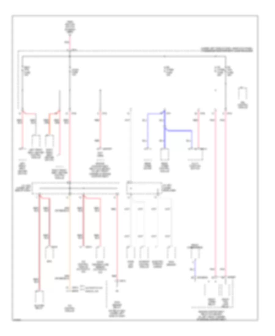
Power Distribution Wiring Diagram (4 of 7) for Hyundai Elantra Touring GLS 2010
List of elements for Power Distribution Wiring Diagram (4 of 7) for Hyundai Elantra Touring GLS 2010:
Power Distribution Wiring Diagram (5 of 7) for Hyundai Elantra Touring GLS 2010
List of elements for Power Distribution Wiring Diagram (5 of 7) for Hyundai Elantra Touring GLS 2010:
Power Distribution Wiring Diagram (6 of 7) for Hyundai Elantra Touring GLS 2010
List of elements for Power Distribution Wiring Diagram (6 of 7) for Hyundai Elantra Touring GLS 2010:
Power Distribution Wiring Diagram (7 of 7) for Hyundai Elantra Touring GLS 2010
List of elements for Power Distribution Wiring Diagram (7 of 7) for Hyundai Elantra Touring GLS 2010: