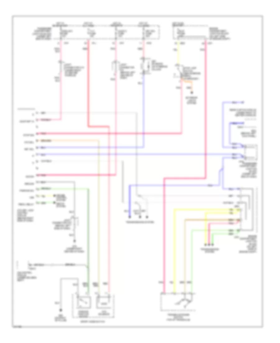
SHIFT INTERLOCK
Shift Interlock Wiring Diagram for Hyundai Azera Limited 2009
List of elements for Shift Interlock Wiring Diagram for Hyundai Azera Limited 2009:
- (behind left side of dash)
- (on steering column)
- (under front of center console)
- Acc/on
- Atm key lock control module (behind right side of dash)
- Atm sol
- Atm solenoid
- Audio 2 fuse 10a
- B/up fuse 10a
- Bcm (behind left kick panel)
- Cruise control system
- Engine compartment junction block (on left side of engine compt)
- Exterior lights system
- G18 (under right center of dash)
- G26 (on right "b" pillar)
- Ground
- Hot at all times
- Hot in acc or on
- Hot in on or start
- I/p-e
- I/p-f
- I/p-j
- Ims control module (under driver's seat)
- Jc01
- Je02
- Joint connector m-10
- Joint connector m-3 (behind left center of dash)
- Joint connector m-5
- Key sol
- Key sol fuse 20a
- Key solenoid
- M28-c
- Module 2 fuse 10a
- On/start in
- Parking position switch
- Parking sw
- Passenger compartment junction block (under left end of dash)
- Pedal relay
- Pnk
- R p
- Rear curtain module (under front of center console)
- Red
- S08-c
- Seats system
- Sport mode switch
- Stop lamp switch (above brake pedal, on bracket)
- Stop sig
- Tilt fuse 15a
- Transaxle range switch (top of transaxle)
- Transmissions system
- Vss
 English