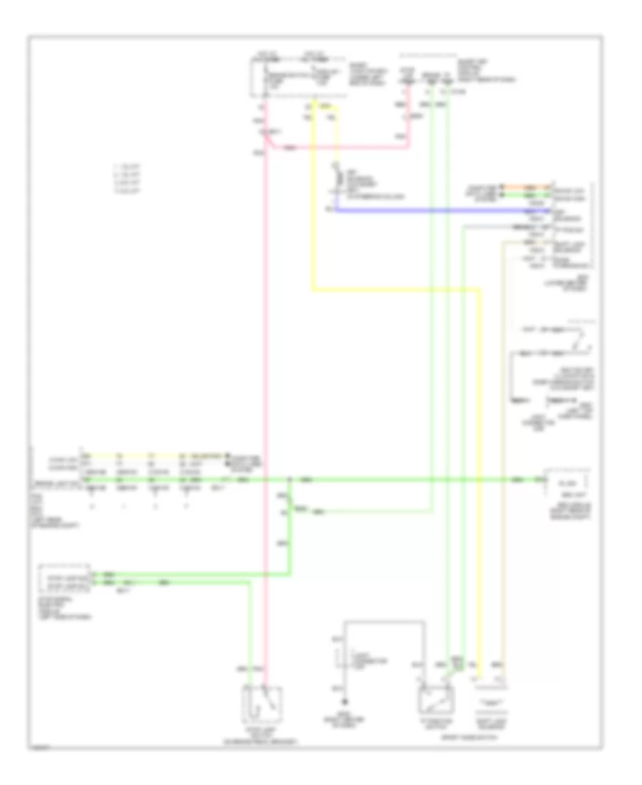
SHIFT INTERLOCK
Shift Interlock Wiring Diagram for Hyundai Elantra SE 2014
List of elements for Shift Interlock Wiring Diagram for Hyundai Elantra SE 2014:
- "p" pos
- "p" pos sw
- "p" position switch
- (lower center
- (or pnk)
- (right center of dash)
- 1.8l a/t
- 1.8l m/t
- 2.0l a/t
- 2.0l m/t
- B-can high
- B-can low
- Bcm
- Brake light sw
- Brake sig
- Brake switch fuse 10a
- C-can high
- C-can low
- C100-ak
- C100-ma
- C100-mk
- C600-ab
- C600-mk
- Computer data lines system
- Door warning sw
- Ec11
- Em11
- Em61
- Esc module (right rear of engine compt)
- Esc unit
- Gm01 (left top dash panel)
- Gm02
- Hot at all times
- I/p-f
- Ignition key illumination & door warning switch (w/o smart key)
- Joint connector ume
- Joint connector umf
- Key solenoid
- Key solenoid (w/o smart key) (in steering column)
- M02-a
- M02-b
- M02-c
- M13-b
- Module 1 fuse 7.5a
- Nca
- Of dash)
- Pcm (a/t) ecm (m/t) (left rear of engine compt)
- Pnk
- Red
- Rl sig
- Shift lock solenoid
- Smart junction box (under left end of dash)
- Smart key control module (right rear of dash)
- Sport mode switch
- Stop lamp sig
- Stop lamp sw
- Stop lamp switch (on brake pedal bracket)
- Stop lmp pwr
- Stop signal electric module (left side of dash)
 English