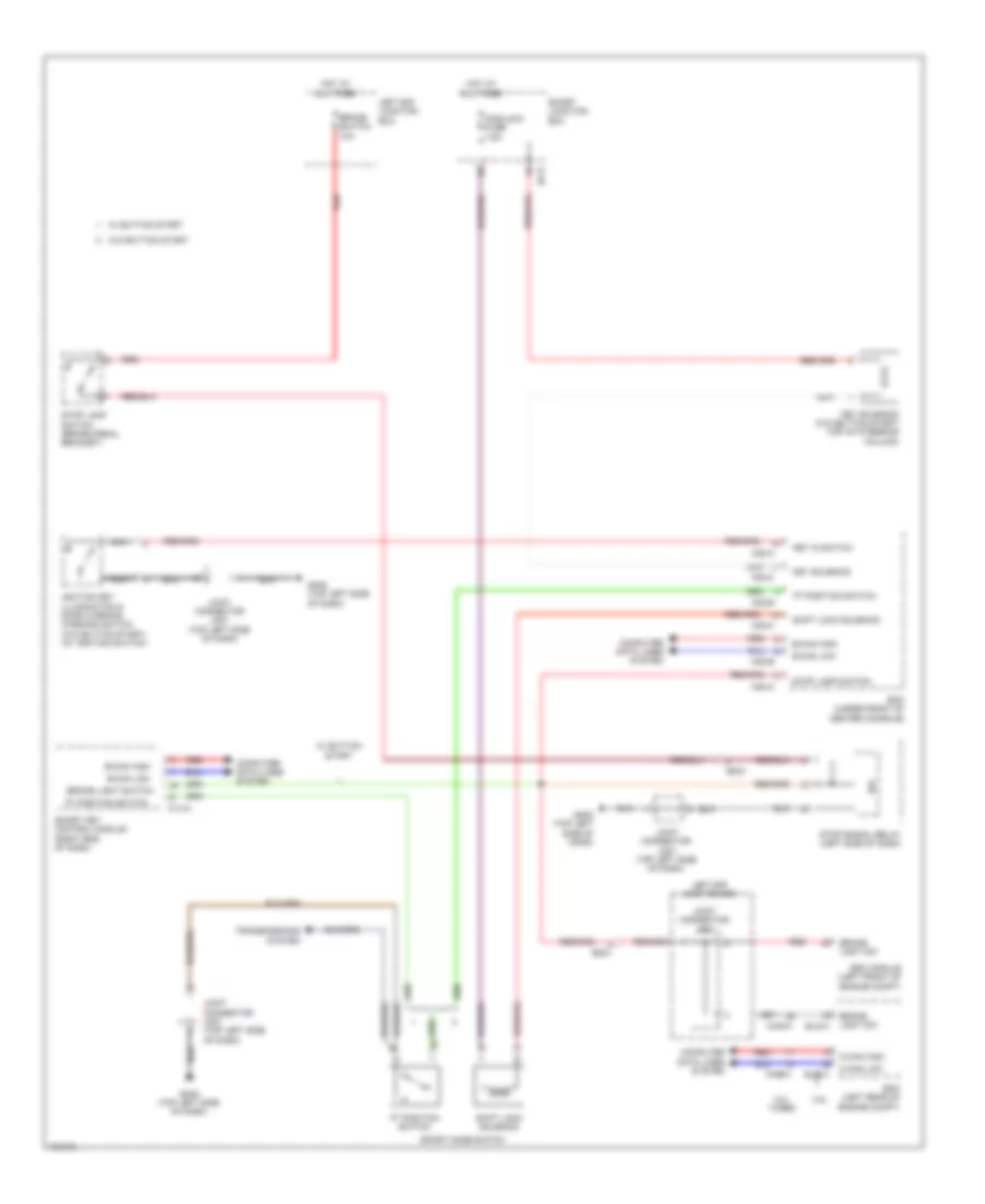
SHIFT INTERLOCK
Shift Interlock Wiring Diagram for Hyundai Genesis Coupe 3.8 Grand Touring 2014
List of elements for Shift Interlock Wiring Diagram for Hyundai Genesis Coupe 3.8 Grand Touring 2014:
- "p" position switch
- 2.0l turbo
- 3.8l
- B-can high
- B-can low
- Bcm (under front of center console)
- Brake
- Brake light sw
- Brake light switch
- Brake switch 10a
- C-can high
- C-can low
- Chg-a
- Chg-k
- Computer data lines system
- Ecm (left rear of engine compt)
- Elg-a
- Em21
- Esc module (left front of engine compt)
- Gm02 (top left side of dash)
- Hot at all times
- I/p-d
- Ignition key illumination & door warning warning switch (w/o button start) (at ignition switch)
- Ips
- Joint connector je68
- Joint connector jm01 (top left side of dash)
- Key in switch
- Key solenoid
- Key solenoid (w/o button start) (top of steering column)
- Left e/r junction box
- Light sw
- M02-a
- M02-b
- M02-c
- M14-a
- Module 5 fuse 7.5a
- Nca
- Red
- Shift lock solenoid
- Smart junction box
- Smart key control module (right end of dash)
- Sport mode switch
- Stop lamp switch
- Stop lamp switch (brake pedal bracket)
- Stop signal relay (left side of dash)
- Transmissions system
- W/ button start
- W/o button start
 English