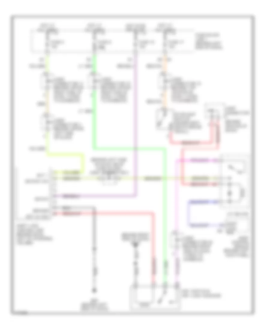
SHIFT INTERLOCK
Shift Interlock Wiring Diagram for Infiniti Q45 2003
List of elements for Shift Interlock Wiring Diagram for Infiniti Q45 2003:
- (behind left side of dash, near fuse block) joint connector 2
- (behind right side of dash) m115
- A/t device
- Bat +
- Body control module (behind left kick panel)
- Detent sw
- Fuse 12 10a
- Fuse 17 15a
- Fuse 6 10a
- Fuse 8 10a
- Fuse block (j/b) 1 (behind left end of dash)
- Ground
- Hot at all times
- Hot in on or start
- Ign sw
- Joint connector (behind center of dash)
- Joint connector 11 (behind upper right side of dash, taped to harness)
- Joint connector 12 (behind top center of dash, taped to harness)
- Joint connector 15 (behind upper right end of dash, taped to harness)
- Joint connector 20 (behind right side of dash, taped to harness)
- Joint connector 3 (behind upper left side of dash)
- Key lk sol
- Key switch & key lock solenoid
- Lock sol
- M25 (behind left side of dash)
- Shift
- Shift lock control unit (behind dash, left of steering column)
- Stoplight switch (on bracket, above brake pedal)
 English