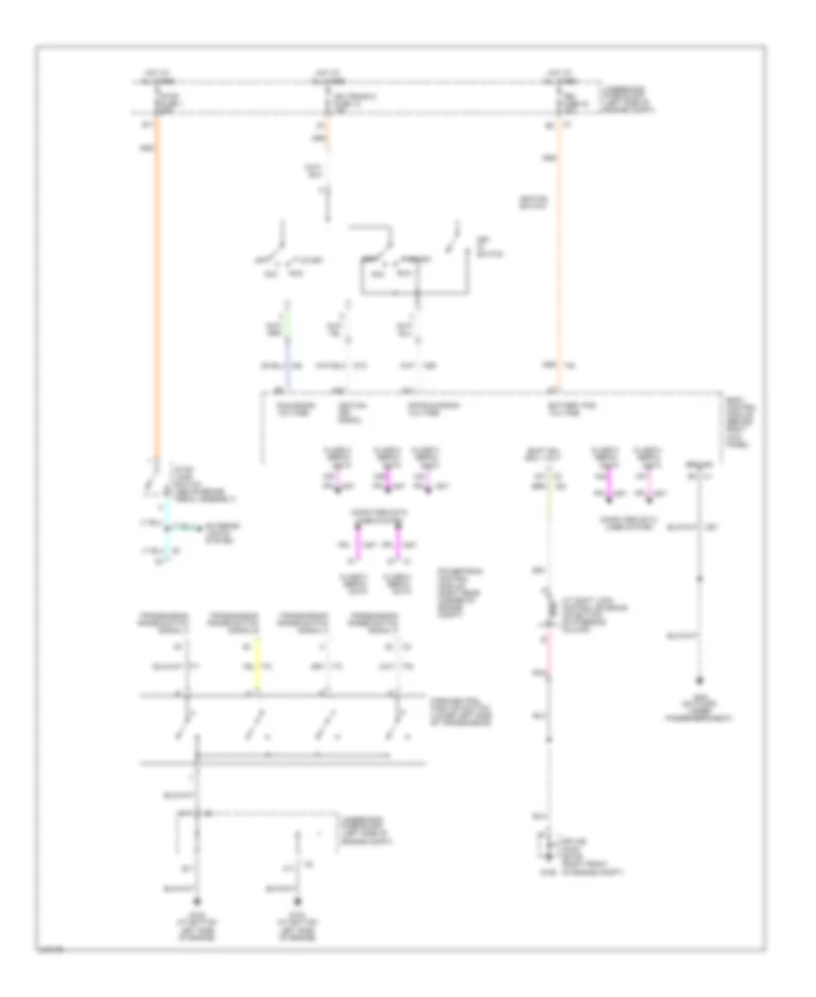
SHIFT INTERLOCK
Shift Interlock Wiring Diagram for Isuzu i-280 LS 2006
List of elements for Shift Interlock Wiring Diagram for Isuzu i-280 LS 2006:
- (on floor, under passenger's seat)
- A/t shift lock control solenoid (on bottom of steering column)
- A11
- A14
- A31 c2
- A38
- A39
- A42
- A44
- A47
- Acc
- B11
- Battery pos voltage
- Body control module (behind right kick panel)
- C1 b3
- C11
- Class 2 serial data
- Computer data lines system
- E11
- Exterior lights system
- G102 (at bottom left side of engine)
- G103 (at bottom left side of engine)
- G106
- G301
- Ground
- Hot at all times
- Ign trans d fuse 10 10a
- Ignition key signal
- Ignition switch
- Key in switch
- Off
- Off/run/crank voltage
- Park/neutral position switch (lower left side of transmission)
- Pnk
- Powertrain control module (right rear corner of engine compt)
- Run
- Run/crank voltage
- Shift sol sply volt
- Splice pack sp106 (right front of engine compt)
- Start
- Stop fuse 1 20a
- Stop lamp switch (above brake pedal assembly)
- Tbc fuse 34 10a
- Transmission range switch signal a
- Transmission range switch signal b
- Transmission range switch signal c
- Transmission range switch signal p
- Underhood fuse block (left side of engine compt)
 English