
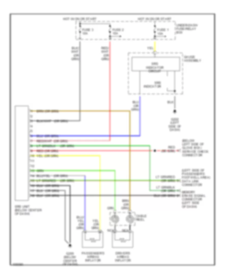
SUPPLEMENTAL RESTRAINTS
Supplemental Restraint Wiring Diagram for Isuzu Oasis S 1998
List of elements for Supplemental Restraint Wiring Diagram for Isuzu Oasis S 1998:
ANTI-LOCK BRAKESAIR CONDITIONINGANTI-THEFTBODY COMPUTERCOOLING FANCRUISE CONTROLCOMPUTER DATA LINESDEFOGGERSEXTERIOR LIGHTSENGINE PERFORMANCEHEADLIGHTSHORNGROUND DISTRIBUTIONINSTRUMENT CLUSTERINTERIOR LIGHTSPOWER DISTRIBUTIONPOWER DOOR LOCKSPOWER WINDOWSPOWER MIRRORSSUPPLEMENTAL RESTRAINTSSHIFT INTERLOCKSPOWER TOP/SUNROOFRADIOSTARTING/CHARGINGWARNING SYSTEMSTRANSMISSIONWIPER/WASHER