TRANSMISSION
Transfer Case Wiring Diagram for Isuzu Ascender Limited 2004

List of elements for Transfer Case Wiring Diagram for Isuzu Ascender Limited 2004:
- (below dash, above accelerator pedal) data link connector
- (on lower left side of engine)
- +5v ref
- 2 lod ind
- 2wd
- 4 hi
- 4 hi ind
- 4 lo
- 4 lo ind
- 4.2l
- 4wd fuse 48 15a
- 4wd lo sig
- 5.3l
- Afwd
- Afwd ind
- Atc fuse 8 25a
- Axle act
- Axle sw
- B11
- Battery
- Brake
- C2 a11
- Class 2 data
- E11
- E5 c3
- Encoder
- Encoder gnd
- Encoder p
- Front axle actuator (lower right front of engine, on oil pan)
- Front sig hi
- Front sig lo
- Front transfer case propshaft speed sensor (on left rear of transfer case)
- G102 (at left side of engine compt)
- G107
- G201
- Ground
- Hot at all times
- Hot in run
- Hot in run or start
- Illum
- Ing e fuse 22 10a
- Instrument panel cluster (ipc)
- Interior lights system
- Lock sol
- Logic
- Motor
- Motor ctrl a
- Motor ctrl b
- Neut
- Neutral
- Neutral ind
- Pnk
- Powertrain control module (4.2l: on left front of engine) (5.3l: on left front of engine compt)
- Rear fuse block (below left rear seat)
- Rear sig hi
- Rear sig lo
- Rear transfer case propshaft speed sensor (on right rear of transfer case)
- Red
- Service 4wd/ awd
- Sp201 (lower right center of dash)
- Splice pack sp205 (behind left side of i/p)
- Sw sig
- Tan
- Transfer case
- Transfer case shift control module (behind left lower dash)
- Transfer case shift control switch
- Under- hood fuse block (on left side of engine compt)
- Underhood fuse block (on left side of engine compt)
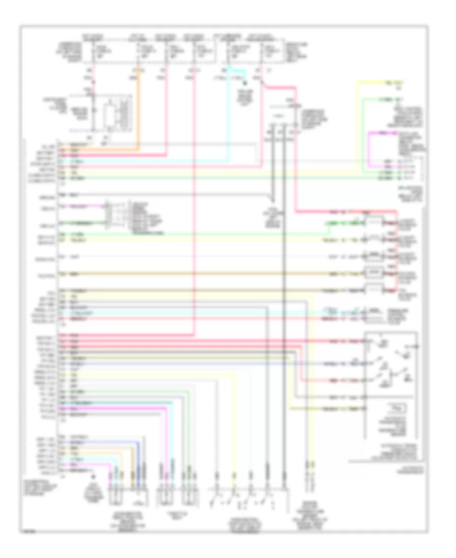
4.2L
4.2L, A/T Wiring Diagram for Isuzu Ascender Limited 2004
List of elements for 4.2L, A/T Wiring Diagram for Isuzu Ascender Limited 2004:
- 1-2 shift red solenoid valve
- 2-3 shift red solenoid valve
- 3-2 shift red solenoid valve
- 4wd circuit (w/ 2-spd transfer case)
- 4wd lo
- A2 c1
- Accelerator pedal position sensor (on accelerator bracket)
- App 1 +5v
- App 1 lo
- App 1 sig
- App 2 +5v
- App 2 lo
- App 2 sig
- Automatic trans- mission fluid pressure manual valve position switch
- Automatic transmission
- Automatic transmission fluid temperature sensor
- Battery
- Body control module (bcm) (beneath left rear seat, on rear fuse block)
- C2 a7
- Class 2 data
- D2 c1
- D2 sw
- D3 sw
- D4 sw
- Data link connector (below dash, above accelerator pedal)
- Down (3-2)
- E3 c2
- Ect ref
- Ect sig
- Engine coolant temperature sensor (on left front of engine, near generator)
- Etc fuse 23 10a
- F14
- G108 (on lower left side of engine)
- Ground
- Hot at all times
- Hot in accy, run or start
- Hot in run or start
- Ign 0 fuse 47 10a
- Ignition
- Ignition 1
- Ing e fuse 22 10a
- Instrument panel cluster (ipc)
- Lo sw
- Mil ind
- P r n d
- Park/neutral position switch (on left side of transmission)
- Pcm 1 fuse 28 15a
- Pcm b fuse 10 20a
- Pcs sol (hi)
- Pcs sol (lo)
- Pnk
- Powertrain control module (on left front of engine)
- Pressure control solenoid valve
- Prndl a in
- Prndl b in
- Prndl c in
- Prndl p in
- Rear fuse block (below left rear seat)
- Red
- Rev sw
- Service engine soon
- Solenoid valve
- Splice pack sp205 (below left side of i/p)
- Ss a (1-2)
- Ss b (2-3)
- Stoplamp in
- Tan
- Tcc
- Tcc pmw red
- Tcc pwm
- Tcc red
- Tfp sw a
- Tfp sw b
- Tfp sw c
- Tft ref
- Tft sig
- Throttle body
- Tp 1 +5v
- Tp 1 lo
- Tp 1 sig
- Tp 2 +5v
- Tp 2 lo
- Tp 2 sig
- Trailer brake control unit
- Underhood fuse block (on left side of engine compt)
- Veh stop fuse 34 15a
- Vehicle speed sensor (2wd: on right rear of trans) (4wd: on left rear of transfer case)
- Vss (hi)
- Vss (lo)
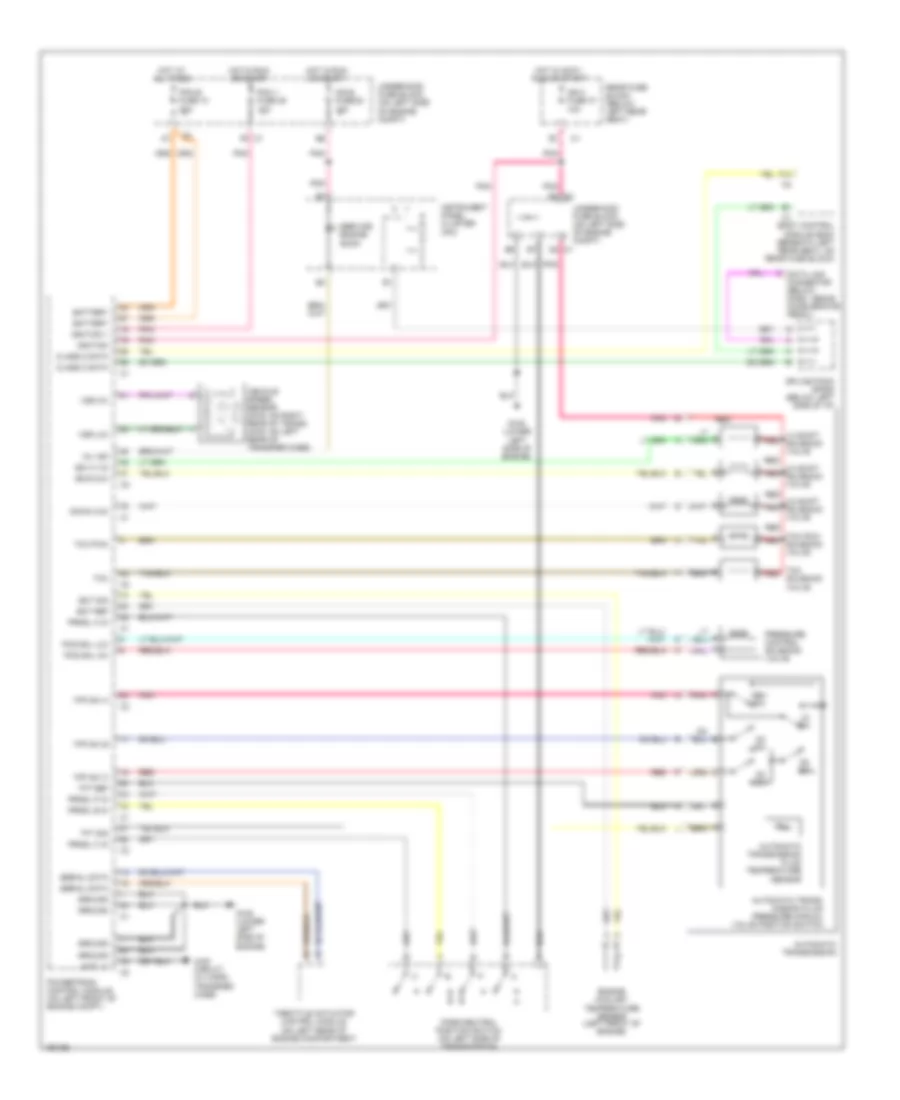
5.3L
5.3L, A/T Wiring Diagram for Isuzu Ascender Limited 2004
List of elements for 5.3L, A/T Wiring Diagram for Isuzu Ascender Limited 2004:
- 1-2 shift red solenoid valve
- 2-3 shift red solenoid valve
- 3-2 shift red solenoid valve
- 4wd circuit (w/ 2-spd transfer case)
- 4wd lo
- Automatic trans- mission fluid pressure manual valve position switch
- Automatic transmission
- Automatic transmission fluid temperature sensor
- Battery
- Body control module (bcm) (beneath left rear seat, on rear fuse block)
- C1 d2
- C1 f5
- C2 e3
- Class 2 data
- D2 sw
- D3 sw
- D4 sw
- Data link connector (below dash, above accelerator pedal)
- Down (3-2)
- Ect ref
- Ect sig
- Engine coolant temperature sensor (left front of engine)
- F14
- G108 (lower left side of engine)
- Ground
- Hot at all times
- Hot in accy, run or start
- Hot in run or start
- Ign 0 fuse 47 10a
- Ignition
- Ignition 1
- Ing e fuse 22 10a
- Instrument panel cluster (ipc)
- Lo sw
- Mil ind
- P r n d
- Park/neutral position switch (on left side of transmission)
- Pcm 1 fuse 28 10a
- Pcm b fuse 10 20a
- Pcs sol (hi)
- Pcs sol (lo)
- Pnk
- Powertrain control module (on left front of engine compt)
- Pressure control solenoid valve
- Prndl a in
- Prndl b in
- Prndl c in
- Prndl p in
- Rear fuse block (below left rear seat)
- Red
- Rev sw
- Serial data
- Service engine soon
- Splice pack sp205 (below left side of i/p)
- Ss a (1-2)
- Ss b (2-3)
- Tan
- Tcc
- Tcc pmw red solenoid valve
- Tcc pwm
- Tcc red solenoid valve
- Tfp sw a
- Tfp sw b
- Tfp sw c
- Tft ref
- Tft sig
- Throttle actuator control module (on left rear of engine compartment
- Underhood fuse block (on left side of engine compt)
- Vehicle speed sensor (2wd: on right rear of trans) (4wd: on left rear of transfer case)
- Vss (hi)
- Vss (lo)