WARNING SYSTEMS
Chime Wiring Diagram for Hyundai Elantra Limited 2013

List of elements for Chime Wiring Diagram for Hyundai Elantra Limited 2013:
- Auto
- B-can high
- B-can low
- B-can transceiver
- Bcm (behind center of dash)
- Buzzer
- Computer data lines system
- Door open ind
- Door warning sw
- Driver door switch (on left "b" pillar)
- Driver door switch signal
- Driver seat belt buckle switch
- Driver seat belt switch
- Gf01 (left "b" pillar)
- Gf07 (under center console)
- Gm01 (left top dash panel)
- Head
- High
- Hot at all times
- Hot in on or start
- I/p-c
- I/p-g
- I/p-h
- Ignition key illumination & door warning switch (w/o smart key) (door warning switch: steering column)
- Ill
- Instrument cluster
- Interior lamp fuse 10a
- Ips control module
- Key ill control
- Leak current autocut device
- Light switch
- Low
- M01-l
- M02-a
- M02-b
- M02-c
- Memory fuse 10a
- Micom
- Module 3 fuse 7.5a
- Multi-function switch
- Nca
- Off
- Pnk
- Red
- Seat belt ind
- Smart junction box (under left side of dash, near kick panel)
- Tail
- Tail lamp sw
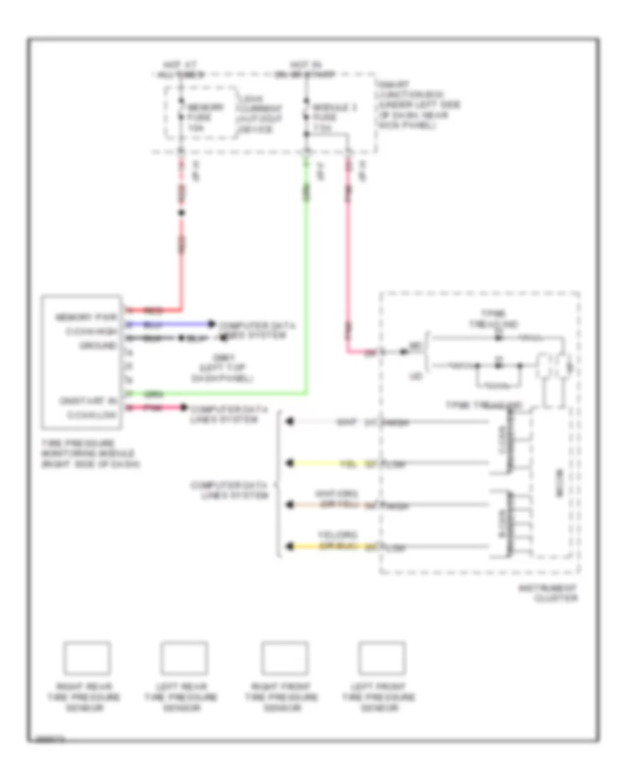
Tire Pressure Monitoring Wiring Diagram for Hyundai Elantra Limited 2013
List of elements for Tire Pressure Monitoring Wiring Diagram for Hyundai Elantra Limited 2013:
- B-can transceiver
- C-can high
- C-can low
- C-can transceiver
- Computer data lines system
- Gm01 (left top dash panel)
- Ground
- High
- Hot at all times
- Hot in on or start
- I/f
- I/p-f
- I/p-h
- Instrument cluster
- Leak current autocut device
- Left front tire pressure sensor
- Left rear tire pressure sensor
- Low
- Memory fuse 10a
- Memory pwr
- Micom
- Module 3 fuse 7.5a
- On/start in
- Pnk
- Red
- Right front tire pressure sensor
- Right rear tire pressure sensor
- Smart junction box (under left side of dash, near kick panel)
- Tire pressure monitoring module (right side of dash)
- Tpms tread ind