POWER DISTRIBUTION
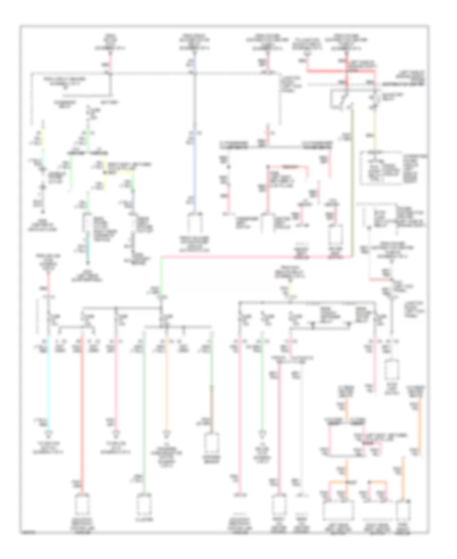
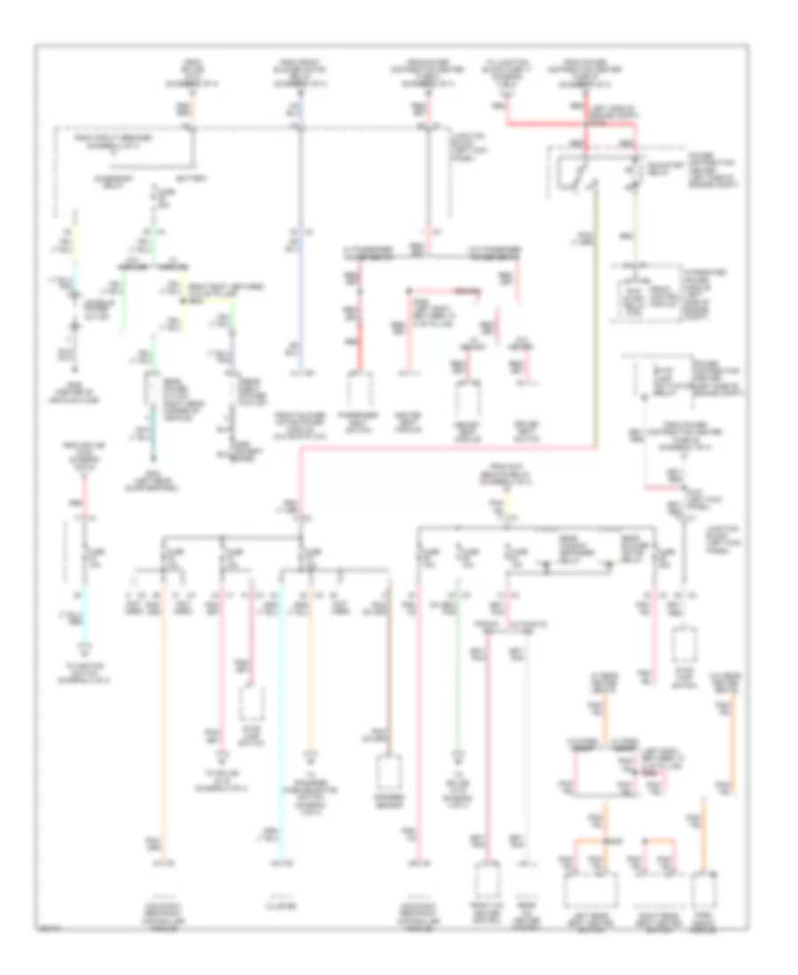
Power Distribution Wiring Diagram, Except Hybrid (1 of 4) for Chrysler Aspen Limited 2009

List of elements for Power Distribution Wiring Diagram, Except Hybrid (1 of 4) for Chrysler Aspen Limited 2009:
- (diagram
- (in left front door) s354
- (left kick panel) junction block
- (left side of engine compt) power distribution center
- (left side of engine compt) s111
- (left side of engine compt) s138
- 2 of 4)
- 4 of 4)
- 87a
- A/c clutch relay
- Accessory delay relay
- Air bag squib)
- Analog clock module
- Anti-lock brakes module
- Auto shut down relay
- Battery
- Between "a" & "b" pillar) s308
- Block
- Circuit breaker 25a
- Cluster
- Door lock switch breakout) s355
- Driver door module
- Driver window/ door lock switch
- For instrument cluster) s210
- For passenger
- Front blower motor relay
- Front control module
- Fuel pump relay
- Fuse 10a
- Fuse 15a
- Fuse 20a
- Fuse 25a
- Fuse 30a
- Fuse 40a
- Fuse 60a
- Fusible link 1 (4 ga- red)
- G207 (right kick panel)
- Generator
- Harness, near battery)
- Instrument panel power outlet
- Integrated power module (left side of engine compt)
- Inverter
- Ipm
- Junction
- Mirror switch
- Module
- Passenger door module
- Passenger window/ door lock switch
- Power liftgate module
- Powertrain control module
- Radio amplifier
- Rear blower motor relay
- Rear window defogger relay
- Red
- Red/ pnk
- Run remote relay
- S143 (left kick panel)
- S205 (breakout
- S211 (breakout for instrument cluster) red
- S352 (in left front door)
- Starter
- Starter motor relay
- Sunroof motor
- Tan/ red
- To 110v
- To fuse 35 (diagram 2 of 4)
- To integrated power module fuse 14 (diagram 3 of 4)
- To junction block (diagram 2 of 4)
- To junction block fuse 24 (diagram 2 of 4)
- To junction block fuse 35 (diagram 2 of 4)
- To splice s121 (diagram 4 of 4)
- To splice s127 (diagram 2 of 4)
- To splice s128 (diagram 2 of 4)
- Trailer tow 4-way wiring
- Trailer tow 7-way wiring
- Transmission control relay
- Wiper high/low relay
- Wiper on/off relay
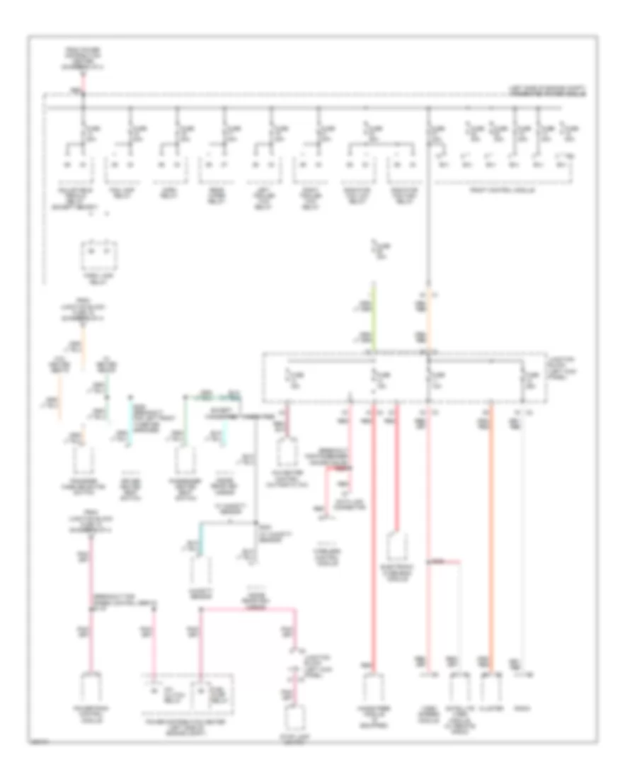
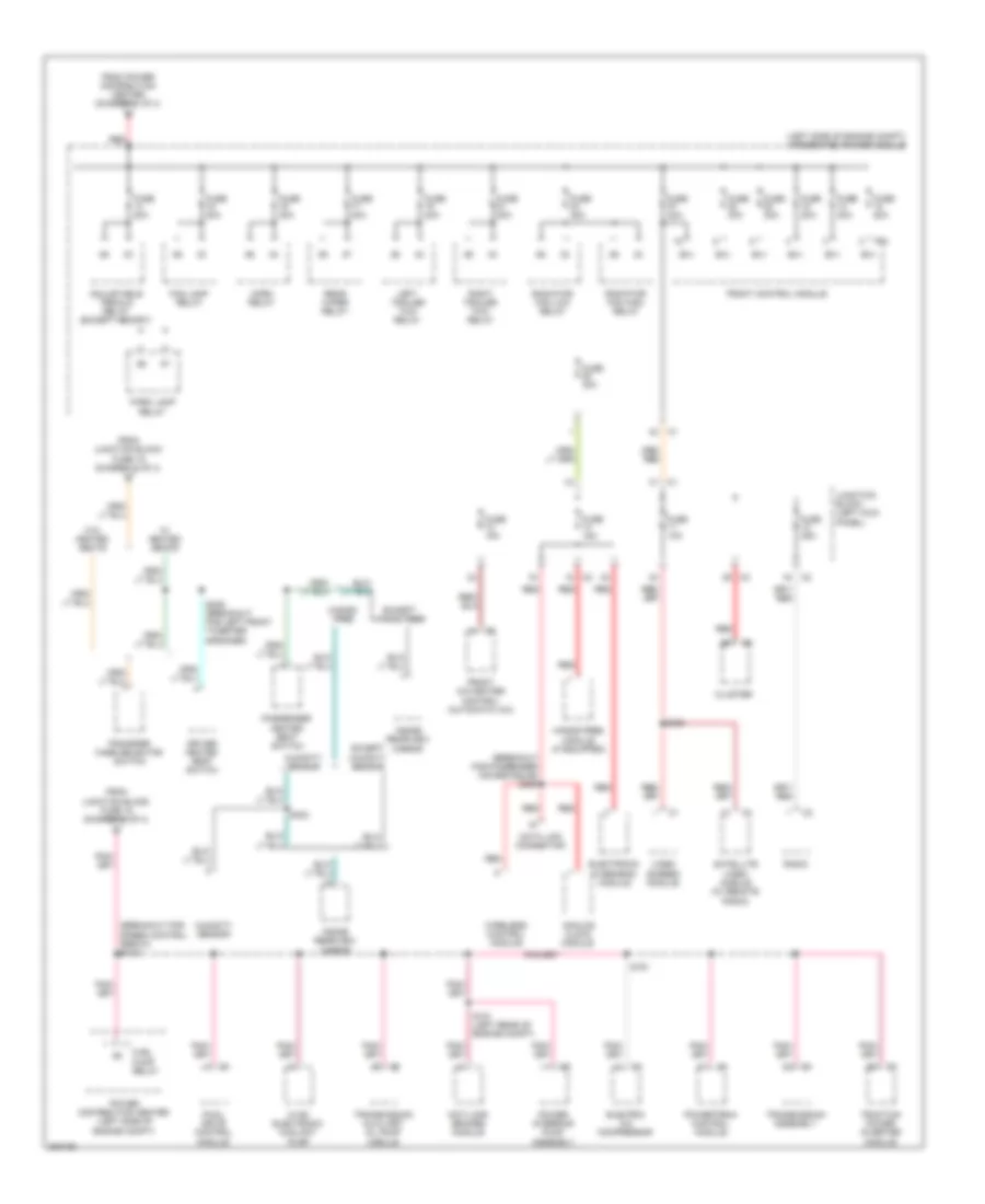
Power Distribution Wiring Diagram, Except Hybrid (2 of 4) for Chrysler Aspen Limited 2009
List of elements for Power Distribution Wiring Diagram, Except Hybrid (2 of 4) for Chrysler Aspen Limited 2009:
- "a" & "b" pillar) s363
- (left side of engine compt) power distribution center
- (not used)
- 87a
- Accessory delay
- Automatic a/c
- Battery
- Cluster
- Console power outlet
- Driver seat switch
- From circuit braker (diagram 1 of 4)
- From front blower motor relay (diagram 1 of 4)
- From power distribution center fuse 25 (diagram 1 of 4)
- From power distribution center fuse 27 (diagram 1 of 4)
- From power distribution center fuse 5 (diagram 1 of 4)
- From run remote relay (diagram 1 of 4)
- From splice s128 (diagram 2 of 4) j
- From splice s143 (diagram 1 of 4)
- Front a/c heater control
- Front blower motor power module (automatic a/c)
- Front control module
- Fuse 10a
- Fuse 20a
- G304 (left rear quarterpanel)
- G306 (center of vehicle floor)
- Heated seat module
- Infrared sensor
- Integrated power module (left side of engine compt)
- Ipm
- Junction block (left kick panel)
- Left rear seat heated switch
- Manual a/c
- Memory seat module
- Occupant restraint controller module
- Park assist module
- Passenger seat switch
- Power distribution center (left side of engine compt)
- Rear a/c heater control
- Rear blower motor relay
- Rear power outlet (right rear corner of vehicle)
- Rear seat power outlet
- Rear window defogger relay
- Red
- Red (left side of engine compt) s128
- Right rear seat heated switch
- Run/ start relay ctrl
- Run/start relay
- S367
- Stop lamp activation relay
- Stop lamp switch
- To ignition switch (diagram 4 of 4)
- To junction block fuse 34 (diagram 2 of 4)
- To splice s116 (diagram 4 of 4)
- To splice s119 (diagram 3 of 4)
- To transfer case selector switch (diagram 3 of 4)
- W/ highline
- W/ memory
- W/ park assist
- W/ passenger power seats
- W/ rear heated seats
- W/o highline
- W/o memory
- W/o park assist
- W/o passenger power seats
- W/o rear heated seats
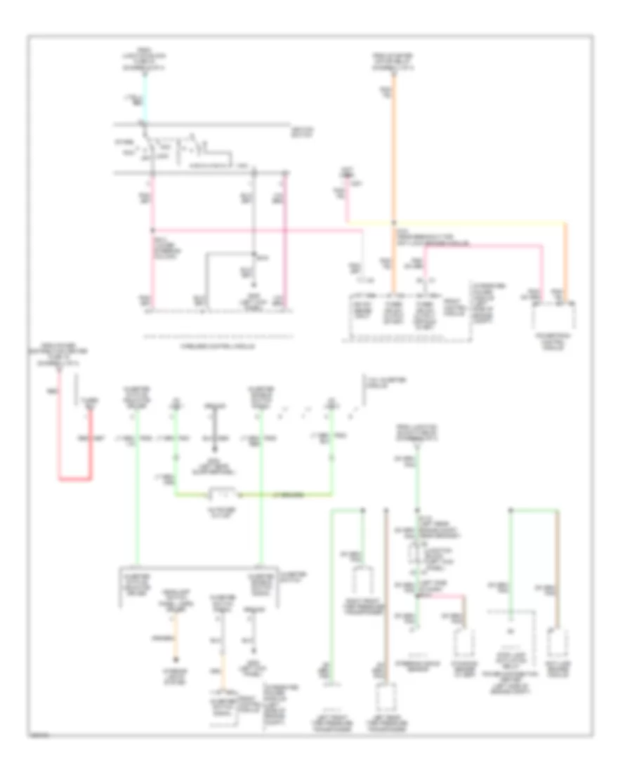
Power Distribution Wiring Diagram, Except Hybrid (3 of 4) for Chrysler Aspen Limited 2009
List of elements for Power Distribution Wiring Diagram, Except Hybrid (3 of 4) for Chrysler Aspen Limited 2009:
- (breakout for passenger air bag squib) s200
- (breakout for speed control servo) s119
- (left side of engine compt) integrated power module
- (w/ humidity sensor)
- A/c clutch relay
- A/c-heater control (automatic a/c)
- Adjustable pedals relay (except memory)
- B(+)
- Cluster
- Data link connector
- Driver heated seat switch
- Electronic overhead module
- Except hands free
- Fog lamp relay
- From junction block fuse 18 (diagram 2 of 4)
- From junction block fuse 19 (diagram 2 of 4)
- From power distribution center (diagram 1 of 4)
- Front control module
- Fuel pump relay
- Fuse 10a
- Fuse 15a
- Fuse 20a
- Fuse 25a
- Fuse 30a
- Fuse 40a
- Hands free
- Hands free module (if equipped)
- Horn relay
- Humidity sensor
- Inside rearview mirror
- Ipm
- Junction block (left kick panel)
- Junction block (left kick panel) c2
- Left trailer tow relay
- Park lamp relay
- Passenger heated seat switch
- Power distribution center (left side of engine compt)
- Powertrain control module
- Radiator fan high relay
- Radiator fan low relay
- Radio
- Rear wiper relay
- Red
- Right trailer tow relay
- S233
- S338
- Satellite video module (w/ remote radio)
- Stop lamp switch
- Transfer case selector switch
- Video screen module
- W/ heated seats
- W/ humidity sensor
- W/o heated seats
- Wireless control module
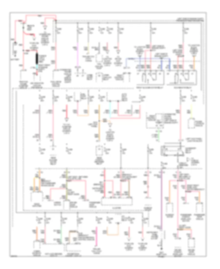
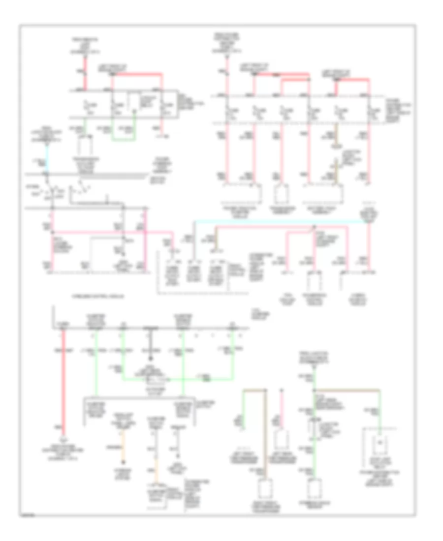
Power Distribution Wiring Diagram, Except Hybrid (4 of 4) for Chrysler Aspen Limited 2009
List of elements for Power Distribution Wiring Diagram, Except Hybrid (4 of 4) for Chrysler Aspen Limited 2009:
- (not used)
- 110v inverter module
- Ac line 1
- Ac line 2
- Ac power outlet
- Acc
- Anti-lock brakes module
- C201
- Dynamics sensor (w/ esp)
- From junction block fuse 26 (diagram 2 of 4)
- From junction block fuse 34 (diagram 2 of 4)
- From power distribution center fuse 16 (diagram 1 of 4)
- From starter motor relay (diagram 1 of 4)
- Front control module
- Fused b(+)
- Fused ign sw output (off-run- start)
- Fused ign sw output (start)
- G208 (left kick panel)
- G304 (left rear quarterpanel)
- Ground
- Headlamp switch panel lamps driver
- Ign sw sense input
- Ignition switch
- Integrated power module (left side of engine compt)
- Interior lights system
- Inverter enable switch signal
- Inverter status indicator driver
- Inverter switch
- Inverter switch signal
- Ipm
- Junction block (left kick panel) c4
- Left front tire pressure transponder
- Left rear tire pressure transponder
- Lock off
- Near grommet)
- Power distribution center (left side of engine compt)
- Powertrain control module
- Red
- Red a957
- Right front tire pressure transponder
- Run
- S121 (near breakout for anti-lock brakes module)
- S214 (lower steering column)
- S218
- Start
- Steering angle sensor
- Stop lamp activation relay
- Wireless control module
Power Distribution Wiring Diagram, Hybrid (1 of 4) for Chrysler Aspen Limited 2009
List of elements for Power Distribution Wiring Diagram, Hybrid (1 of 4) for Chrysler Aspen Limited 2009:
- (diagram
- (in left front door) s354
- (left body, between "a" & "b" pillar) s307
- (left kick panel) junction block
- (left side of engine compt) power distribution center
- (left side of engine compt) s111
- (left side of engine compt) s138
- 2 of 4)
- 4 of 4)
- 87a
- A/c clutch relay
- Accessory delay relay
- Air bag squib)
- Anti-lock brakes module
- Auto shut down relay
- Battery
- Between "a" & "b" pillar) s308
- Block
- Block fuse 35
- Circuit breaker 25a
- Cluster
- Compt) s190
- Door lock switch breakout) s355
- Driver door module
- Driver window/ door lock switch
- Final drive control module
- For instrument cluster) s210
- For passenger
- Front blower motor relay
- Front control module
- Fuel pump relay
- Fuse 10a
- Fuse 15a
- Fuse 20a
- Fuse 25a
- Fuse 30a
- Fuse 40a
- Fuse 50a
- Fuse 60a
- Fusible link 2 (12 ga- red)
- G207 (right kick panel)
- Hev radiator cooling fan module
- Hybrid gateway module
- Instrument panel power outlet
- Integrated power module (left side of engine compt)
- Inverter
- Ipm
- Junction
- Mirror switch
- Module
- Passenger door module
- Passenger window/ door lock switch
- Power liftgate module
- Powertrain control module
- Radio amplifier
- Rear blower motor relay
- Rear window defogger relay
- Red
- Red/ (left side of engine compt) s131
- Red/ pnk
- Red/ tan
- Remote jump post
- Rly ctrl
- Run remote relay
- S143 (left kick panel)
- S154
- S157
- S196
- S205 (breakout
- S211 (breakout for instrument cluster) red
- S352 (in left front door)
- Splice
- Sunroof motor
- Tan/ red
- To 110v
- To fuse 35 (diagram 2 of 4)
- To integrated power module fuse 14 (diagram 3 of 4)
- To junction block (diagram 2 of 4)
- To junction block fuse 24 (diagram 2 of 4)
- To splice
- To splice s127 (diagram 2 of 4)
- To splice s128 (diagram 2 of 4)
- Tpim cooling pump
- Traction power inverter module
- Trailer tow 4-way wiring
- Trailer tow 7-way wiring
- Wiper high/low relay
- Wiper on/off relay
Power Distribution Wiring Diagram, Hybrid (2 of 4) for Chrysler Aspen Limited 2009
List of elements for Power Distribution Wiring Diagram, Hybrid (2 of 4) for Chrysler Aspen Limited 2009:
- (left body, between "a" & "b" pillar) s363
- (not used)
- 87a
- Accessory delay
- Automatic a/c
- Battery
- Cluster
- Console power outlet
- Driver seat switch
- From circuit breaker (diagram 1 of 4)
- From front blower motor relay (diagram 1 of 4)
- From power distribution center fuse 25 (diagram 1 of 4)
- From power distribution center fuse 27 (diagram 1 of 4)
- From power distribution center fuse 5 (diagram 1 of 4)
- From run remote relay (diagram 1 of 4)
- From splice s128 (diagram 2 of 4)
- From splice s143 (diagram 1 of 4)
- Front a/c heater control
- Front blower motor power module (automatic a/c)
- Front control module
- Fuse 10a
- Fuse 20a
- G304 (left rear quarterpanel)
- G306 (center of vehicle floor)
- Heated seat module
- Infrared sensor
- Integrated power module (left side of engine compt)
- Ipm
- Junction block (left kick panel)
- Left rear seat heated switch
- Manual a/c
- Memory seat module
- Occupant restraint controller module
- Park assist module
- Passenger seat switch
- Power distribution center (left side of engine compt)
- Rear a/c heater control
- Rear blower motor relay
- Rear power outlet (right rear corner of vehicle)
- Rear seat power outlet
- Rear window defogger relay
- Red
- Red (left side of engine compt) s128
- Right rear seat heated switch
- Run/ start relay ctrl
- Run/start relay
- S367
- Stop lamp activation relay
- Stop lamp switch
- To ignition switch (diagram 4 of 4)
- To junction block fuse 17 (diagram 2 of 4)
- To splice s116 (diagram 4 of 4)
- To splice s119 (diagram 3 of 4)
- To transfer case selector switch (diagram 3 of 4)
- W/ highline
- W/ memory
- W/ park assist
- W/ passenger power seats
- W/ rear heated seats
- W/o highline
- W/o memory
- W/o park assist
- W/o passenger power seats
- W/o rear heated seats
Power Distribution Wiring Diagram, Hybrid (3 of 4) for Chrysler Aspen Limited 2009
List of elements for Power Distribution Wiring Diagram, Hybrid (3 of 4) for Chrysler Aspen Limited 2009:
- (breakout for passenger air bag squib) s200
- (breakout for speed control servo) s119
- (left side of engine compt) integrated power module
- Adjustable pedals relay (except memory)
- Analog clock module
- Anti-lock brakes module
- B(+)
- Cluster
- Data link connector
- Driver heated seat switch
- Electric a/c compressor
- Electronic overhead module
- Except hands free
- Except humidity sensor
- Final drive control module
- Fog lamp relay
- From junction block fuse 18 (diagram 2 of 4)
- From junction block fuse 19 (diagram 2 of 4)
- From power distribution center (diagram 1 of 4)
- Front a/c-heater control (automatic a/c)
- Front control module
- Fuel pump relay
- Fuse 10a
- Fuse 15a
- Fuse 20a
- Fuse 25a
- Fuse 30a
- Fuse 40a
- Hands free module (if equipped)
- Hands- free
- Horn relay
- Humidity sensor
- Hvac electronic coolant pump
- Inside rearview mirror
- Ipm
- Junction block (left kick panel)
- Left trailer tow relay
- Park lamp relay
- Passenger heated seat switch
- Power distribution center (left side of engine compt)
- Power steering pump assembly
- Powertrain control module
- Radiator fan high relay
- Radiator fan low relay
- Radio
- Rear wiper relay
- Red
- Right trailer tow relay
- S151 (left rear of engine compt)
- S191
- S206 (breakout for left front tweeter speaker)
- S233
- S338
- Satellite video module (w/ remote radio)
- Traction power inverter module
- Transfer case selector switch
- Transmission assembly
- Transmission auxiliary oil pump module
- Video screen module
- W/ heated seats
- W/o heated seats
- Wireless control module
Power Distribution Wiring Diagram, Hybrid (4 of 4) for Chrysler Aspen Limited 2009
List of elements for Power Distribution Wiring Diagram, Hybrid (4 of 4) for Chrysler Aspen Limited 2009:
- (left front of engine compt) s152
- (left front of engine compt) s154
- (left front of engine compt) s157
- 110v inverter module
- Ac line 1
- Ac line 2
- Ac power outlet
- Acc
- Battery pack assembly
- From junction block fuse 26 (diagram 2 of 4)
- From junction block fuse 34 (diagram 2 of 4)
- From power distribution center fuse 20 (diagram 1 of 4)
- From power distribution center fuse 4 (diagram 1 of 4)
- From remote jump post (diagram 1 of 4)
- Front control module
- Fuse 10a
- Fuse 20a
- Fuse 25a
- Fuse 40a
- Fuse 80a
- Fused b(+)
- Fused ign sw output (off-run- start)
- Fused ign sw output (run- start)
- Fused ign sw output (start)
- G208 (left kick panel)
- G304 (left rear quarterpanel)
- Ground
- Headlamp switch panel lamps driver
- Hev power distribution center
- Hvac electric coolant pump
- Hybrid gateway module
- Ignition switch
- Integrated power module (left side of engine compt)
- Interior lights system
- Inverter enable switch signal
- Inverter status indicator driver
- Inverter switch
- Inverter switch signal
- Ipm
- Junction block (left kick panel)
- Junction block (left kick panel) c4
- Left front tire pressure transponder
- Left rear tire pressure transponder
- Lock off
- Power distribution center (left side of engine compt)
- Power steering pump assembly
- Power traction inverter module
- Powertrain control module
- Red
- Red a957
- Right front tire pressure transponder
- Run
- S153 (left front of engine compt)
- S214 (lower steering column)
- S218
- Start
- Steering angle sensor
- Stop lamp activation relay
- Tpim cooling pump
- Transmission assembly
- Transmission auxiliary oil pump module
- Vacuum pump relay
- Wireless control module