ANTI-LOCK BRAKES
Anti-lock Brake Wiring Diagrams for Dodge Durango 1999
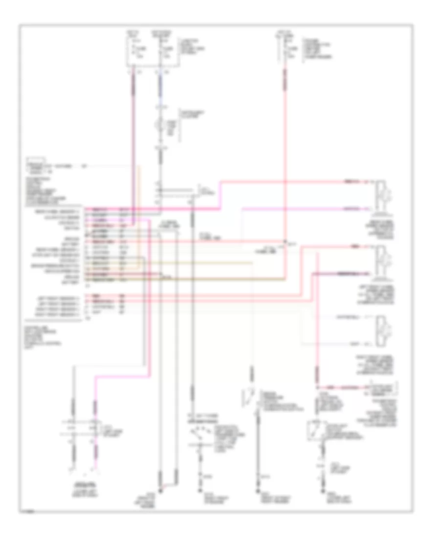
List of elements for Anti-lock Brake Wiring Diagrams for Dodge Durango 1999:
- (231 t-case)
- (242 t-case)
- (lower left side of dash)
- 4wd switch (left side of transfer case) 1 part time 2 full time 3 neutral 4 2wd
- 4x4 switch sense
- A10
- A20
- B10
- B113
- B114
- Battery
- Brake pressure switch
- Brake pressure switch (in brake system combination switch)
- Ccd bus (+)
- Ccd bus (-)
- Controller anti-lock brake (mounted on top of hydraulic control unit)
- Data link connector
- Forward of washer fluid reservoir)
- Fuse 10a
- Fuse 40a
- G100 (front of left front fender)
- G101 (front of right front fender)
- G107
- G119 (right front of engine)
- G202 (lower left end of dash)
- Ground
- Hot at all times
- Hot in run
- Hot in run or start
- Ignition
- Instrument cluster
- J/c 1 (in pdc)
- J/c 3 (left side of dash)
- J/c 4 (left side of dash)
- Junction block (on left end of dash)
- K29
- Left front sensor (+)
- Left front sensor (-)
- Left front wheel speed sensor (w/ all wheel abs) (on left front steering knuckle)
- Part time 4x4 ind
- Power distribution center (on left inner fender)
- Powertrain control module (on right front inner fender,
- Powertrain control module (on right front inner fender, forward of washer fluid reservoir)
- Rear wheel sensor (+)
- Rear wheel sensor (-)
- Rear wheel speed sensor (on top of differential housing)
- Red
- Right front sensor (+)
- Right front sensor (-)
- Right front wheel speed sensor (w/ all wheel abs) (on right front steering knuckle)
- S108
- S113
- S117
- S119
- S158 (in wiring trough, on left side of eng compt)
- Stoplight sw sense sig
- Stoplight sw sense signal
- Stoplight switch (on brake pedal support bracket)
- Vehicle speed sig
- Vehicle speed signal
- W/ all wheel abs
- W/ rear wheel abs
 English