ANTI-LOCK BRAKES
Anti-lock Brakes Wiring Diagram for Dodge Durango 2004
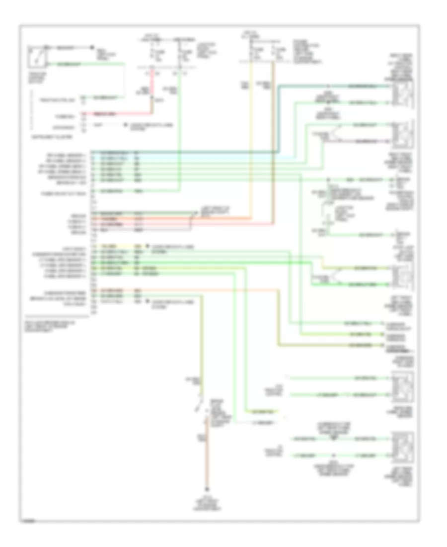
List of elements for Anti-lock Brakes Wiring Diagram for Dodge Durango 2004:
- (in breakout for left rear wheel speed sensor) s358
- (left front of engine compt) g114
- (or b22)
- (or b222)
- (right rear wheel) (w/ traction control) right rear abs wheel speed sensor
- A107
- A111
- Anti-lock brakes module (left front of engine compartment)
- B20
- B23
- B24
- B29
- B924
- Brake
- Brake fluid level sensor (left rear of engine compt)
- Brake fluid level sw sense
- Brake sw 1 sig
- Can b bus(-)
- Can c bus(+)
- Can c bus(-)
- Computer data lines
- Computer data lines system
- D64
- D65
- F500
- Fuse 10a
- Fuse 15a
- Fuse 20a
- Fuse 40a
- Fuse b (+)
- Fused b(+)
- Fused ign sw out (run)
- G-sensor (right side of dash)
- G-sensor force feed
- G-sensor force sig
- G-sensor force sig return
- G-sensor force sig rt
- G114 (left front of engine compartment)
- G208 (left kick panel)
- Ground
- Hot at all times
- Hot in run
- Instrument cluster
- Junction block (left kick panel)
- Left front abs wheel speed sensor (left front wheel)
- Left rear abs wheel speed sensor (left rear wheel)
- Lf wheel spd sensor (+)
- Lf wheel spd sensor (-)
- Power distribution center (left side of engine compartment)
- Powertrain control module (right side of engine compt)
- Rear abs wheel speed sensor
- Rf wheel speed sens (+)
- Rf wheel speed sens (-)
- Right front abs wheel speed sensor (right front wheel)
- Rr wheel sensor (+)
- Rr wheel sensor (-)
- S210
- S334 (near breakout for left rear wheel speed sensor)
- S360 (near right rear wheel)
- S361 (near right rear wheel)
- Sensor-g force sig
- Stop lamp switch (left side of dash)
- Sw 1 c3 sig
- Sw 1 sig
- System
- Tan/ red
- Tan/red
- Traction control switch
- Traction ctrl sw
- Twisted pair
- W/ traction control
- W/o traction control
- Wheel spd sensor (+)
- Wheel spd sensor (-)
- Z923
 English