ANTI-LOCK BRAKES
Anti-lock Brake Wiring Diagrams for Dodge Intrepid R/T 2001
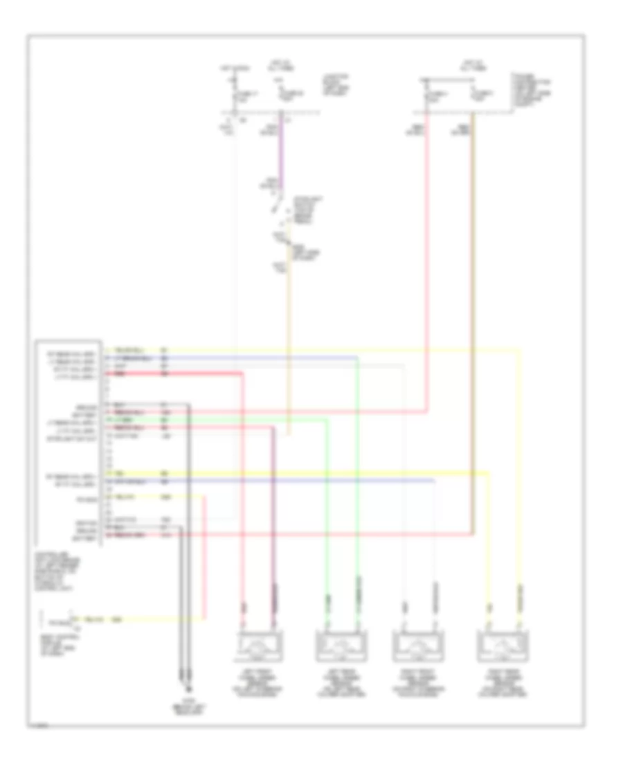
List of elements for Anti-lock Brake Wiring Diagrams for Dodge Intrepid R/T 2001:
- A10
- A20
- Battery
- Body control module (at left end of dash)
- Controller anti-lock brake (at left fender side shield, on bottom of hydraulic control unit)
- D25
- F20
- Fuse 17 10a
- Fuse 20 20a
- Fuse h 30a
- Fuse k 40a
- G106 (behind left headlamp)
- Ground
- Hot at all times
- Hot in run
- Ignition
- Junction block (left end of dash)
- L50
- Left front wheel speed sensor (on left steering knuckle boss)
- Left rear wheel speed sensor (on left rear caliper adapter)
- Lt ft whl spd +
- Lt ft whl spd -
- Lt rear whl spd +
- Lt rear whl spd -
- Pci bus
- Power distribution center (on left side of engine compt)
- Red
- Right front wheel speed sensor (on right steering knuckle boss)
- Right rear wheel speed sensor (on right rear caliper adapter)
- Rt ft whl spd +
- Rt ft whl spd -
- Rt rear whl spd +
- Rt rear whl spd -
- S205 (left side of dash)
- Stoplight sw out
- Stoplight switch (top of brake pedal)
 English