BODY CONTROL MODULES
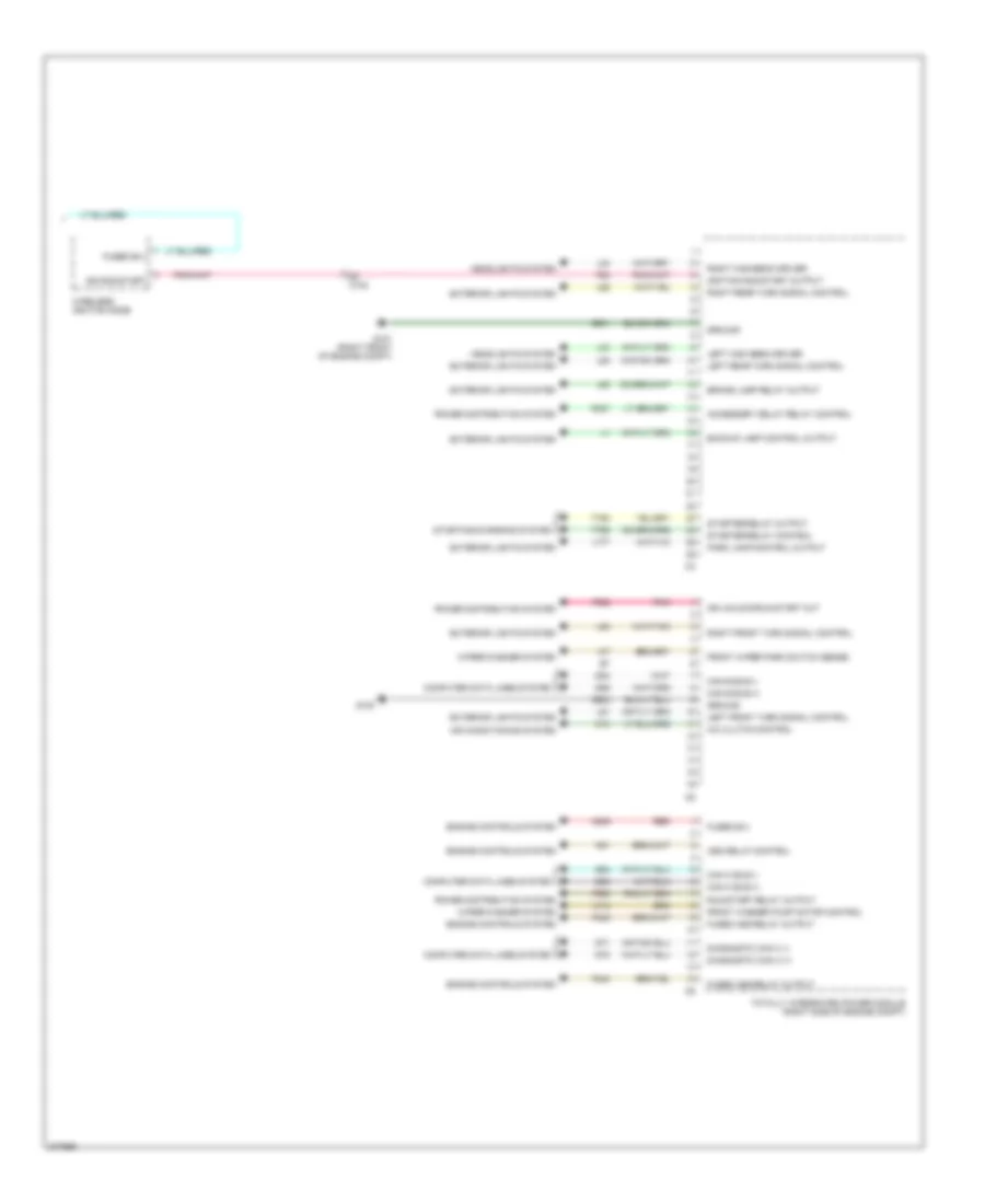
Body Control Modules Wiring Diagram (1 of 2) for Dodge Challenger SE 2010

List of elements for Body Control Modules Wiring Diagram (1 of 2) for Dodge Challenger SE 2010:
Body Control Modules Wiring Diagram (2 of 2) for Dodge Challenger SE 2010
List of elements for Body Control Modules Wiring Diagram (2 of 2) for Dodge Challenger SE 2010: