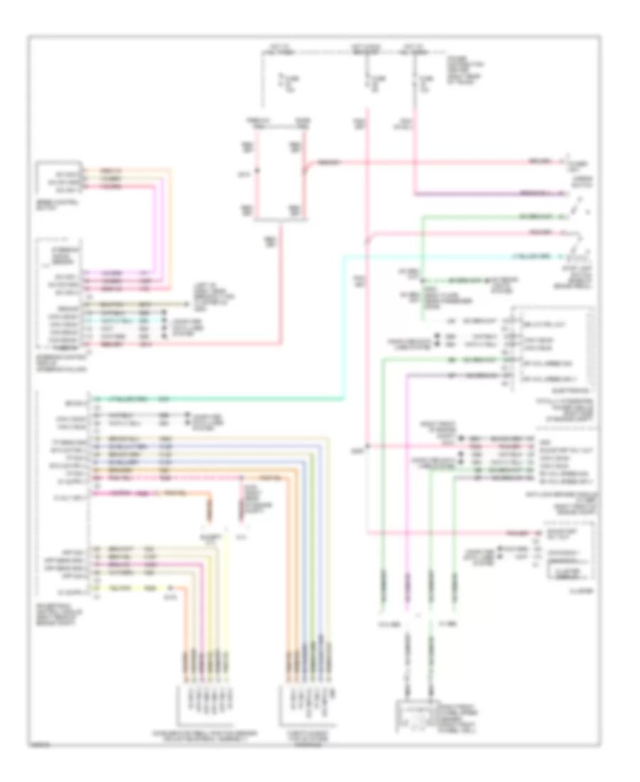
CRUISE CONTROL
Cruise Control Wiring Diagram for Dodge Challenger SRT-8 2008
List of elements for Cruise Control Wiring Diagram for Dodge Challenger SRT-8 2008:
- (left of dash, near breakout for cluster c3) g202
- (right front of engine compt)
- 5 volt sply
- 5.7l
- 5v sply
- A913
- Accelerator pedal position sensor (adjustable pedal assembly)
- Anti-lock brakes module (w/ esp) (right front of engine compt)
- App gnd 1
- App gnd 2
- App sens gnd 1
- App sens gnd 2
- App sig 1
- App sig 2
- B16
- Base tpm
- Br lp ctrl out
- Br sig 2
- Can b bus +
- Can b bus -
- Can b bus+
- Can b bus-
- Can c bus+
- Can c bus-
- Cluster
- Cluster display
- Computer data lines system
- D54
- D55
- D64
- D65
- Electronics
- Etc motor (+)
- Etc motor (-)
- Etc mtr (+)
- Etc mtr (-)
- Except 5.7l
- Exterior lights system
- F202
- F852
- F855
- F856
- Fuse 10a
- Fuse 5a
- Fused b(+)
- Fused b+
- G101
- Gnd
- Ground
- Hot at all times
- Hot in run or start
- K122
- K124
- K126
- K167
- K22
- K23
- K29
- K400
- K922
- L53
- Mirror switch
- Nca
- Power distribution center (right rear of trunk)
- Powertrain control module (right rear of engine compt)
- Premium tpm
- Rf whl speed sig
- Rf whl speed sply
- Right front wheel speed sensor (right front wheel well)
- Run/start rly out
- S/c sig 1
- S/c sig 2
- S/c sw gnd
- S105 (right rear of engine compt)
- S175
- S209
- S302 (body floor, near passenger door)
- S310
- Speed control switch
- Steering angle sensor
- Steering control module (steering column)
- Stop lamp switch (base of brake pedal)
- Throttle body (top of intake manifold)
- Totally integrated power module (right side of engine compt)
- Tp sens gnd
- Tp sig 1
- Tp sig 2
- V71
- V72
- V937
- W/ abs
- W/o abs
- Z910
- Z931
 English