ENGINE PERFORMANCE
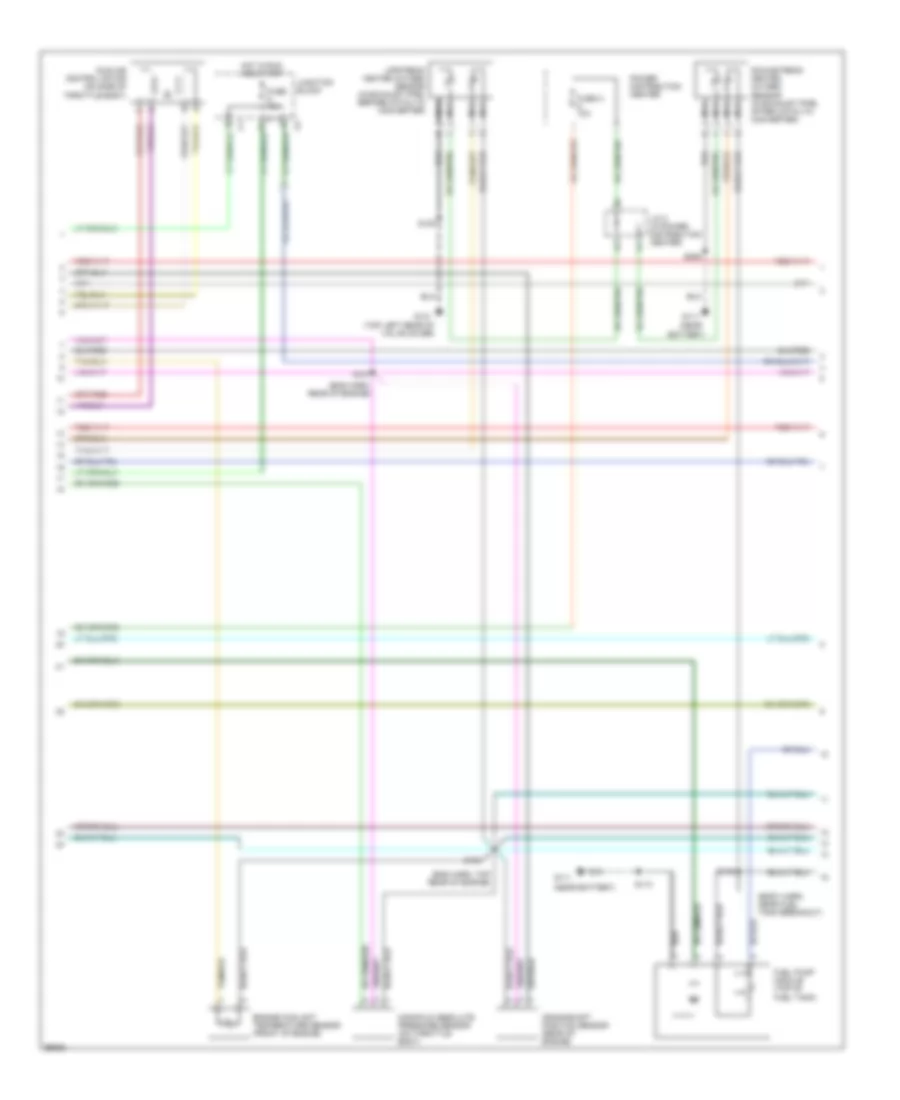
2.5L
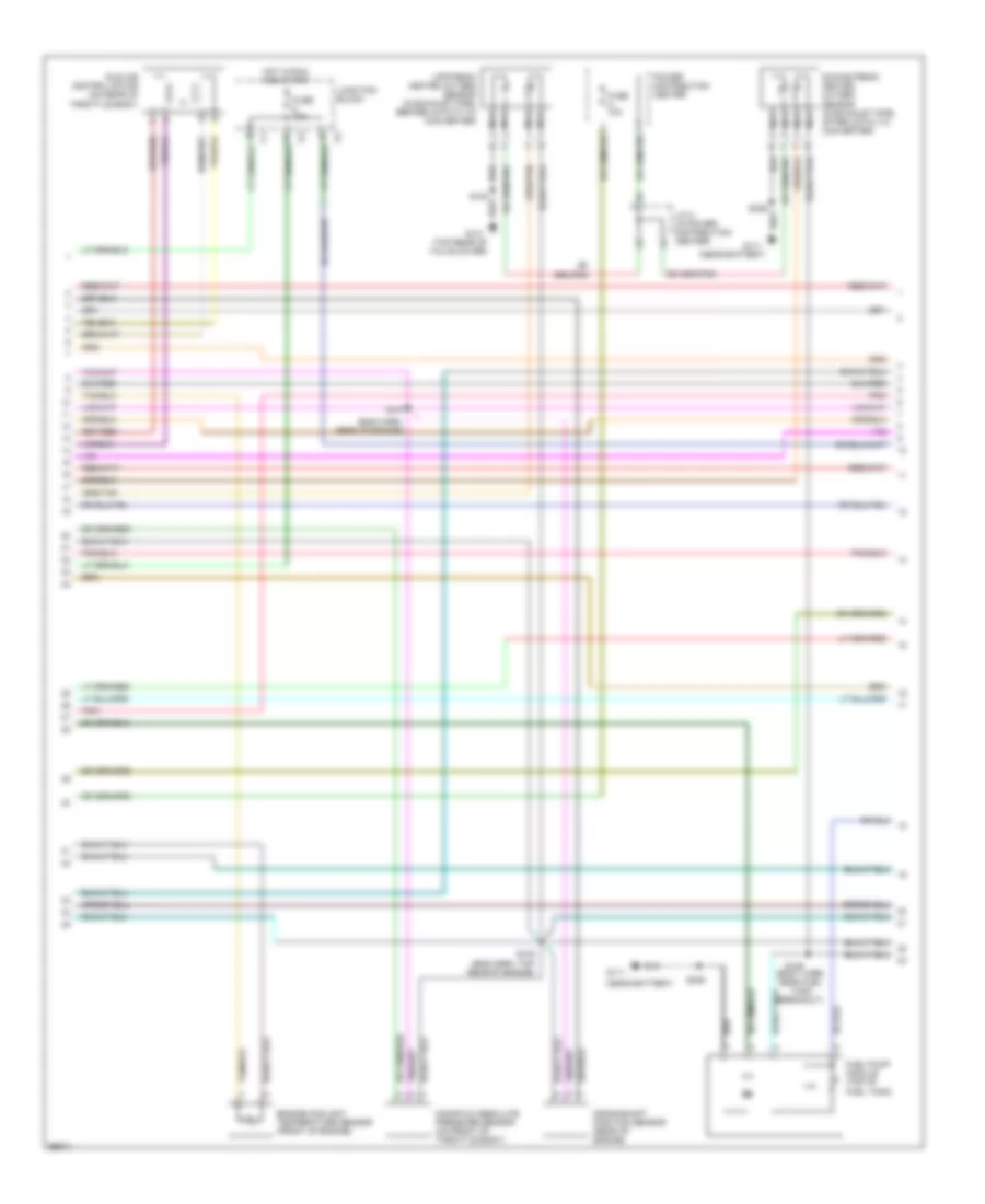
2.5L, Engine Performance Wiring Diagrams (1 of 3) for Dodge Dakota R/T 1998

List of elements for 2.5L, Engine Performance Wiring Diagrams (1 of 3) for Dodge Dakota R/T 1998:
- (in distributor)
- (near distributor)
- (top left of valve cover)
- A14
- Anti-lock brake controller (left front of eng compt)
- Automatic shutdown relay
- Automatic transmission (left side of transmission)
- Cam pos sns
- Camshaft position sensor
- Coil 1 driver
- Crnk pos sns
- Distributor
- Dn ho2s in
- Ect sens in
- F18
- Fuel injectors
- Fuel pump relay
- Fused b(+)
- G131 (top left rear of valve cover)
- G60
- Gen field drv
- Ground
- Iat sens in
- Idle air 1
- Idle air 2
- Idle air 3
- Idle air 4
- Ign power
- Ignition coil (near distributor)
- Inj 1 driver
- Inj 2 driver
- Inj 3 driver
- Inj 4 driver
- J/c 1 (in power distribution center)
- J/c 2 (in power distri- bution center)
- K11
- K12
- K13
- K14
- K141
- K19
- K20
- K21
- K22
- K24
- K341
- K39
- K40
- K44
- K59
- K60
- K99
- Map sens in
- Nca
- Oil pres sns
- Oil pressure sensor
- Power distribution center
- Power steering pressure switch (near power steering pump)
- Powertrain control module (right fender side shield)
- Psp sw
- S101 (eng harn, right side of firewall)
- S105
- S106 (eng harn, center rear of engine)
- S108
- Sensor grd
- Starting/ charging system
- Tan
- Tps sens in
- Up ho2s in
- Vss in
- Z12 (or z1)
2.5L, Engine Performance Wiring Diagrams (2 of 3) for Dodge Dakota R/T 1998
List of elements for 2.5L, Engine Performance Wiring Diagrams (2 of 3) for Dodge Dakota R/T 1998:
- (body harn, near fuel tank breakout)
- (eng harn, rear of engine)
- (eng harn, top rear of engine)
- (near
- (near battery)
- (top left rear of valve cover)
- Battery)
- Crankshaft position sensor (rear of engine)
- Downstream heated oxygen sensor (in exhaust pipe, after catalyic converter)
- Engine coolant temperature sensor (front of engine)
- Fuel pump module (top of fuel tank)
- Fuse 10a
- Fuse a 10a
- G111
- G131
- Hot in run and start
- Idle air control motor (on side of throttle body)
- J/c 2 (in power distribution center)
- Junction block
- Manifold absolute pressure sensor (on throttle body)
- Nca
- Power distribution center
- S103
- S107
- S108
- S113
- S149
- S306
- Upstream heated oxygen sensor (in exhaust pipe, before catalyic converter)
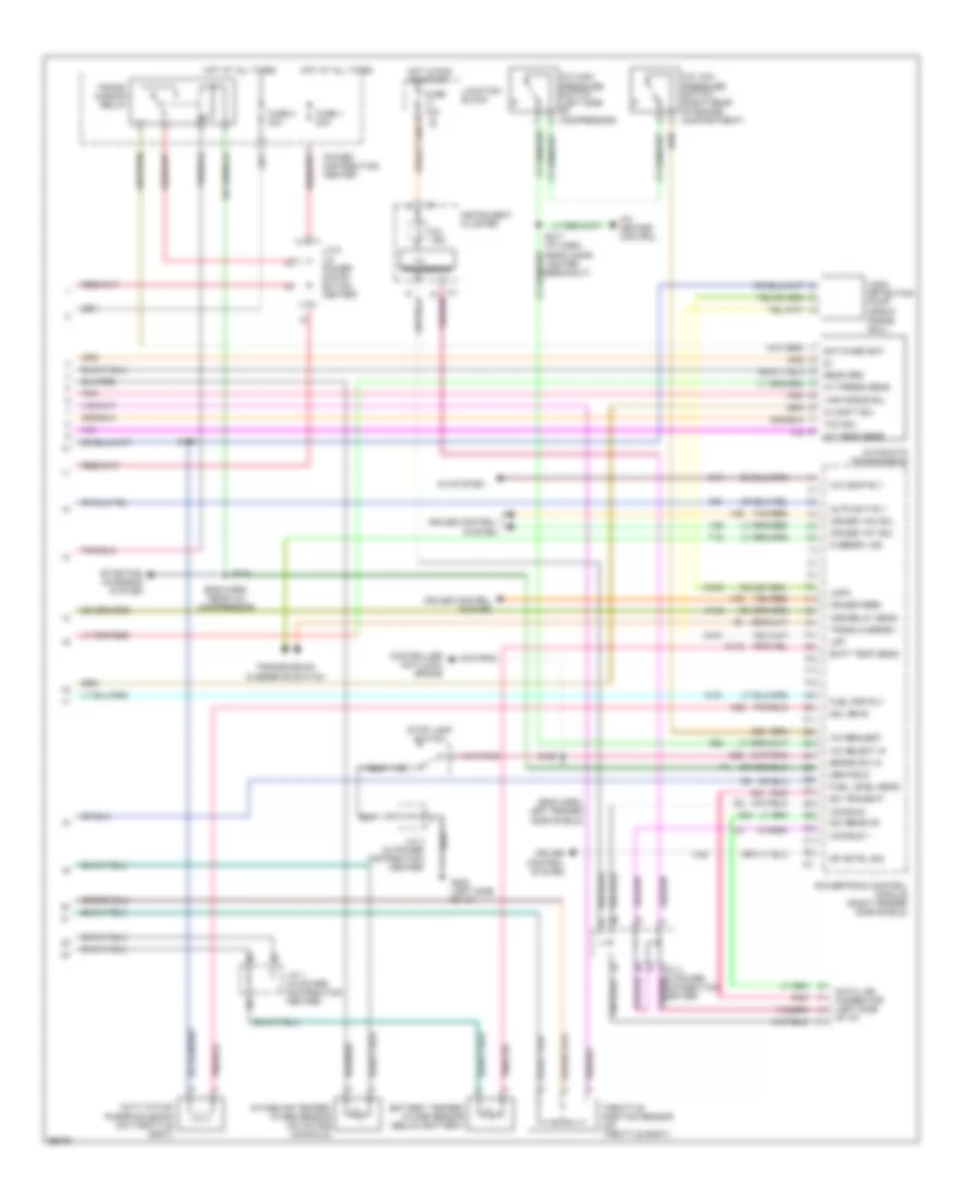
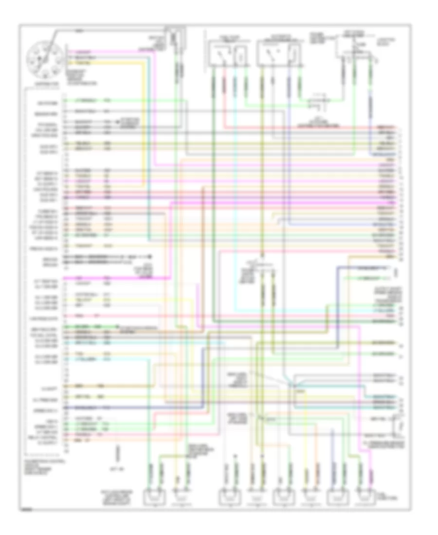
2.5L, Engine Performance Wiring Diagrams (3 of 3) for Dodge Dakota R/T 1998
List of elements for 2.5L, Engine Performance Wiring Diagrams (3 of 3) for Dodge Dakota R/T 1998:
- (eng harn, left fender side shield)
- A/c comp rly
- A/c heater control
- A/c high pressure switch (left side of compressor)
- A/c low pressure switch (right rear of engine compartment)
- A/c request
- A/c select in
- A/c system
- A142
- Asd relay sens
- Auto sht rly
- Batt temp sens
- Battery temper- ature sensor (below battery)
- Brake sw in
- C13
- C20
- C27
- C32
- C90
- Ccd bus +
- Ccd bus -
- Controller anti-lock brake
- Cruise control system
- Cruise feed
- Cruise vac sol
- Cruise vnt sol
- D20
- D21
- Data link connector (left side of dash)
- Duty cycle/ purge solenoid (on throttle body)
- Fuel level sens
- Fuel pmp rly
- Fuse 1 20a
- Fuse 10a
- Fuse 3 30a
- G100
- G101
- G202 (left side of i/p)
- Gen field
- Hot at all times
- Hot in run or start
- I/o
- Instrument cluster
- Intake air temper- ature sensor (on intake manifold)
- J/c 1 (in power distribution center)
- J/c 2 (in power distri- bution center)
- J/c 3 (in power distribution center)
- J/c 4 (in power distribution center)
- Junction block
- K118
- K151
- K29
- K51
- K52
- Ldp
- Ldpa
- Leak detection pump (front frame rail)
- Mil ind.
- Overdrv ind
- Pnk
- Power distribution center
- Powertrain control module (right fender side shield)
- Processor
- Rad fan cntrl
- S129
- S158
- S217 (i/p harn, near cigar lighter breakout)
- Sci receive
- Sci transmit
- Sol drvr
- Sp cntrl sig
- Starting/ charging system
- Stop lamp switch
- T18
- Tan/red
- Throttle position sensor (on throtlle body)
- Trans overdrv
- Transmission overdrive switch
- V32
- V35
- V36
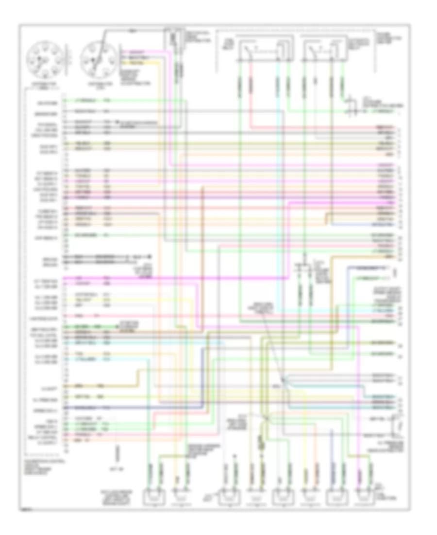
3.9L
3.9L, Engine Performance Wiring Diagrams (1 of 3) for Dodge Dakota R/T 1998
List of elements for 3.9L, Engine Performance Wiring Diagrams (1 of 3) for Dodge Dakota R/T 1998:
- (eng harn, right side of firewall)
- (engine harness, center rear of engine) s106
- (in distributor)
- 3-4 shift
- 5.2l only
- A/t sen sig
- A/t temp sig
- A14
- Anti-lock brake controller (left front of engine compt)
- Automatic shutdown relay
- Cam pos sns
- Camshaft position sensor
- Coil driver
- Crnk pos sns
- Distributor (3.9l)
- Distributor (5.2l)
- Dn ho2s in
- Ect sens in
- F18
- Fuel injectors
- Fuel pump relay
- Fused b(+)
- G131 (top rear of valve cover)
- G60
- Gen field drv
- Ground
- Iat sens in
- Idle air 1
- Idle air 2
- Idle air 3
- Idle air 4
- Ign power
- Ignition coil (near distributor)
- Inj 1 driver
- Inj 2 driver
- Inj 3 driver
- Inj 4 driver
- Inj 5 driver
- Inj 6 driver
- Inj 7 driver
- Inj 8 driver
- J/c 1 (in power distribution center)
- J/c 2 (in power distri- bution center)
- K11
- K12
- K13
- K14
- K19
- K20
- K21
- K22
- K24
- K26
- K28
- K341
- K38
- K39
- K40
- K44
- K441
- K54
- K58
- K59
- K60
- Map sens in
- Nca
- Oil pres sns
- Oil pressure sensor (near distributor)
- Output shaft speed sensor (side of transmission)
- P/n signal
- Pnk
- Power distribution center
- Powertrain control module (right fender side shield)
- Relay control
- S101
- S105
- S110 (eng harn, left side of engine)
- Sensor grd
- Speed sig (+)
- Speed sig (-)
- Starting/ charging system
- Starting/charging system
- T13
- T14
- T25
- T34
- T41
- T60
- Tan
- Tcc sol cntrl
- Tps sens in
- Up ho2s in
- Var frce cntr
- Vss in
- Z12 (or z1)
3.9L, Engine Performance Wiring Diagrams (2 of 3) for Dodge Dakota R/T 1998
List of elements for 3.9L, Engine Performance Wiring Diagrams (2 of 3) for Dodge Dakota R/T 1998:
- (eng harn, rear of engine)
- (eng harn, top rear of engine)
- (near battery)
- (top rear of valve cover)
- Crankshaft position sensor (rear of engine)
- Downstream heated oxygen sensor (in exhaust pipe, after catalyic converter)
- Engine coolant temperature sensor (front of engine)
- Fuel pump module (top of fuel tank)
- Fuse 10a
- Fuse a 10a
- G111
- G131
- Hot in run and start
- Idle air control motor (on rear of throttle body)
- J/c 2 (in power distribution center)
- Junction block
- Manifold absolute pressure sensor (on front of throttle body)
- Nca
- Pnk
- Power distribution center
- S103
- S107
- S108
- S149 (body harn, near fuel tank breakout)
- S306
- Upstream heated oxygen sensor (in exhaust pipe, before catatytic converter)
3.9L, Engine Performance Wiring Diagrams (3 of 3) for Dodge Dakota R/T 1998
List of elements for 3.9L, Engine Performance Wiring Diagrams (3 of 3) for Dodge Dakota R/T 1998:
- (eng harn, left fender side shield)
- (eng harn, near a/c compressor)
- 3-4 shft sol
- A/c comp rly
- A/c heater control
- A/c high pressure switch (left side of compressor)
- A/c low pressure switch (right rear of engine compartment)
- A/c request
- A/c select in
- A/c system
- A/t press sens
- A/t temp sens
- A142
- Asd relay sens
- Auto sht rly
- Automatic transmission
- Batt temp sens
- Battery temper- ature sensor (below battery)
- Brake sw in
- C13
- C20
- C32
- C90
- Ccd bus +
- Ccd bus -
- Controller anti-lock brake
- Cruise control system
- Cruise feed
- Cruise vac sol
- Cruise vnt sol
- D20
- D21
- Data link connector (left side of i/p)
- Distribution center)
- Duty cycle/ purge solenoid (on throttle body)
- Fuel level sens
- Fuel pmp rly
- Fuse 1 20a
- Fuse 10a
- Fuse 3 30a
- G100
- G101
- G202 (left side of i/p)
- Gen field
- Hot at all times
- Hot in run or start
- I/o
- Instrument cluster
- Intake air temper- ature sensor (on intake manifold)
- J/c 1 (in power distribution center)
- J/c 2 (in power distri- bution center)
- J/c 3 (in power
- J/c 4 (in power distribution center)
- Junction block
- K118
- K151
- K29
- K51
- K52
- Ldp
- Ldpa
- Leak detection pump (front frame rail)
- Mil ind.
- Overdrv ind
- Pnk
- Power distribution center
- Powertrain control module (right fender side shield)
- Processor
- S104
- S129
- S158
- S217 (i/p harn, near cigar lighter breakout)
- Sci receive
- Sci transmit
- Sens grd
- Sol drvr
- Sp cntrl sig
- Starting/ charging system
- Stop lamp switch
- Switched bat
- T18
- Tan/red
- Tcc sol
- Throttle position sensor (on throttle body)
- Trans overdrv
- Trans- mission relay
- Transmission overdrive switch
- V32
- V35
- V36
- Var force sol
5.2L
5.2L, Engine Performance Wiring Diagrams (1 of 3) for Dodge Dakota R/T 1998
List of elements for 5.2L, Engine Performance Wiring Diagrams (1 of 3) for Dodge Dakota R/T 1998:
- (eng harn, right side of firewall)
- (engine harness, center rear of engine) s106
- (in distributor)
- 3-4 shift
- 5.2l only
- A/t sen sig
- A/t temp sig
- A14
- Anti-lock brake controller (left front of engine compt)
- Automatic shutdown relay
- Cam pos sns
- Camshaft position sensor
- Coil driver
- Crnk pos sns
- Distributor (3.9l)
- Distributor (5.2l)
- Dn ho2s in
- Ect sens in
- F18
- Fuel injectors
- Fuel pump relay
- Fused b(+)
- G131 (top rear of valve cover)
- G60
- Gen field drv
- Ground
- Iat sens in
- Idle air 1
- Idle air 2
- Idle air 3
- Idle air 4
- Ign power
- Ignition coil (near distributor)
- Inj 1 driver
- Inj 2 driver
- Inj 3 driver
- Inj 4 driver
- Inj 5 driver
- Inj 6 driver
- Inj 7 driver
- Inj 8 driver
- J/c 1 (in power distribution center)
- J/c 2 (in power distri- bution center)
- K11
- K12
- K13
- K14
- K19
- K20
- K21
- K22
- K24
- K26
- K28
- K341
- K38
- K39
- K40
- K44
- K441
- K54
- K58
- K59
- K60
- Map sens in
- Nca
- Oil pres sns
- Oil pressure sensor (near distributor)
- Output shaft speed sensor (side of transmission)
- P/n signal
- Pnk
- Power distribution center
- Powertrain control module (right fender side shield)
- Relay control
- S101
- S105
- S110 (eng harn, left side of engine)
- Sensor grd
- Speed sig (+)
- Speed sig (-)
- Starting/ charging system
- Starting/charging system
- T13
- T14
- T25
- T34
- T41
- T60
- Tan
- Tcc sol cntrl
- Tps sens in
- Up ho2s in
- Var frce cntr
- Vss in
- Z12 (or z1)
5.2L, Engine Performance Wiring Diagrams (2 of 3) for Dodge Dakota R/T 1998
List of elements for 5.2L, Engine Performance Wiring Diagrams (2 of 3) for Dodge Dakota R/T 1998:
- (eng harn, rear of engine)
- (eng harn, top rear of engine)
- (near battery)
- (top rear of valve cover)
- Crankshaft position sensor (rear of engine)
- Downstream heated oxygen sensor (in exhaust pipe, after catalyic converter)
- Engine coolant temperature sensor (front of engine)
- Fuel pump module (top of fuel tank)
- Fuse 10a
- Fuse a 10a
- G111
- G131
- Hot in run and start
- Idle air control motor (on rear of throttle body)
- J/c 2 (in power distribution center)
- Junction block
- Manifold absolute pressure sensor (on front of throttle body)
- Nca
- Pnk
- Power distribution center
- S103
- S107
- S108
- S149 (body harn, near fuel tank breakout)
- S306
- Upstream heated oxygen sensor (in exhaust pipe, before catatytic converter)
5.2L, Engine Performance Wiring Diagrams (3 of 3) for Dodge Dakota R/T 1998
List of elements for 5.2L, Engine Performance Wiring Diagrams (3 of 3) for Dodge Dakota R/T 1998:
- (eng harn, left fender side shield)
- (eng harn, near a/c compressor)
- 3-4 shft sol
- A/c comp rly
- A/c heater control
- A/c high pressure switch (left side of compressor)
- A/c low pressure switch (right rear of engine compartment)
- A/c request
- A/c select in
- A/c system
- A/t press sens
- A/t temp sens
- A142
- Asd relay sens
- Auto sht rly
- Automatic transmission
- Batt temp sens
- Battery temper- ature sensor (below battery)
- Brake sw in
- C13
- C20
- C32
- C90
- Ccd bus +
- Ccd bus -
- Controller anti-lock brake
- Cruise control system
- Cruise feed
- Cruise vac sol
- Cruise vnt sol
- D20
- D21
- Data link connector (left side of i/p)
- Distribution center)
- Duty cycle/ purge solenoid (on throttle body)
- Fuel level sens
- Fuel pmp rly
- Fuse 1 20a
- Fuse 10a
- Fuse 3 30a
- G100
- G101
- G202 (left side of i/p)
- Gen field
- Hot at all times
- Hot in run or start
- I/o
- Instrument cluster
- Intake air temper- ature sensor (on intake manifold)
- J/c 1 (in power distribution center)
- J/c 2 (in power distri- bution center)
- J/c 3 (in power
- J/c 4 (in power distribution center)
- Junction block
- K118
- K151
- K29
- K51
- K52
- Ldp
- Ldpa
- Leak detection pump (front frame rail)
- Mil ind.
- Overdrv ind
- Pnk
- Power distribution center
- Powertrain control module (right fender side shield)
- Processor
- S104
- S129
- S158
- S217 (i/p harn, near cigar lighter breakout)
- Sci receive
- Sci transmit
- Sens grd
- Sol drvr
- Sp cntrl sig
- Starting/ charging system
- Stop lamp switch
- Switched bat
- T18
- Tan/red
- Tcc sol
- Throttle position sensor (on throttle body)
- Trans overdrv
- Trans- mission relay
- Transmission overdrive switch
- V32
- V35
- V36
- Var force sol
5.9L
5.9L, Engine Performance Wiring Diagrams (1 of 3) for Dodge Dakota R/T 1998
List of elements for 5.9L, Engine Performance Wiring Diagrams (1 of 3) for Dodge Dakota R/T 1998:
- (eng harn, center rear of engine) s106
- (eng harn, left side of engine)
- (eng harn, right side of firewall)
- (in distributor)
- 3-4 shift
- A/t sen sig
- A/t temp sig
- A14
- Anti-lock brake controller (left front of engine compt)
- Automatic shutdown relay
- Cam pos sns
- Camshaft position sensor
- Coil driver
- Crnk pos sns
- Distributor
- Ect sens in
- F18
- Fuel injectors
- Fuel pump relay
- Fuse 10a
- Fused b(+)
- G131 (top rear of valve cover)
- G60
- Gen field drv
- Ground
- Hot in run and start
- Iat sens in
- Idle air 1
- Idle air 2
- Idle air 3
- Idle air 4
- Ign power
- Ignition coil (near distributor)
- Inj 1 driver
- Inj 2 driver
- Inj 3 driver
- Inj 4 driver
- Inj 5 driver
- Inj 6 driver
- Inj 7 driver
- Inj 8 driver
- J/c 1 (in power distribution center)
- J/c 2 (in power distri- bution center)
- Junction block
- K11
- K12
- K13
- K14
- K141
- K19
- K20
- K21
- K22
- K24
- K241
- K26
- K28
- K341
- K38
- K39
- K40
- K44
- K441
- K54
- K58
- K59
- K60
- Lt up ho2s in
- Map sens in
- Nca
- Oil pres sns
- Oil pressure sensor (near distributor)
- Output shaft speed sensor (side of transmission)
- P/n signal
- Pnk
- Pos dn ho2s in
- Power distribution center
- Powertrain control module (right fender side shield)
- Pre dn ho2s in
- Relay control
- Rt up ho2s in
- S101
- S105
- S110
- Sensor grd
- Speed sig (+)
- Speed sig (-)
- Starting/ charging system
- Starting/charging system
- T13
- T14
- T25
- T34
- T41
- T60
- Tan
- Tcc sol cntrl
- Tps sens in
- Var frce cntr
- Vss in
- Z12 (or z1)
5.9L, Engine Performance Wiring Diagrams (2 of 3) for Dodge Dakota R/T 1998
List of elements for 5.9L, Engine Performance Wiring Diagrams (2 of 3) for Dodge Dakota R/T 1998:
- (body harn, near fuel tank breakout)
- (eng harn, rear of engine)
- (eng harn, top rear of engine)
- (in exhaust pipe, before catalytic converter) pre-catalyst downstream heated oxygen sensor
- (in left exhaust downpipe) left upstream heated oxygen sensor
- (in right exhaust downpipe) right upstream heated oxygen sensor
- (near battery)
- Crankshaft position sensor (rear of engine)
- Engine coolant temperature sensor (front of engine)
- Fuel pump module (top of fuel tank)
- Fuse a 10a
- G111
- G111 (near battery)
- G131 (top rear of valve cover)
- Idle air control motor (on rear of throttle body)
- J/c 2 (in power distribution center)
- Manifold absolute pressure sensor (on front of throttle body)
- Nca
- Pnk
- Post-catalyst downstream heated oxygen sensor (after catalytic converter)
- Power distribution center
- S103
- S107
- S130
- S149
- S306
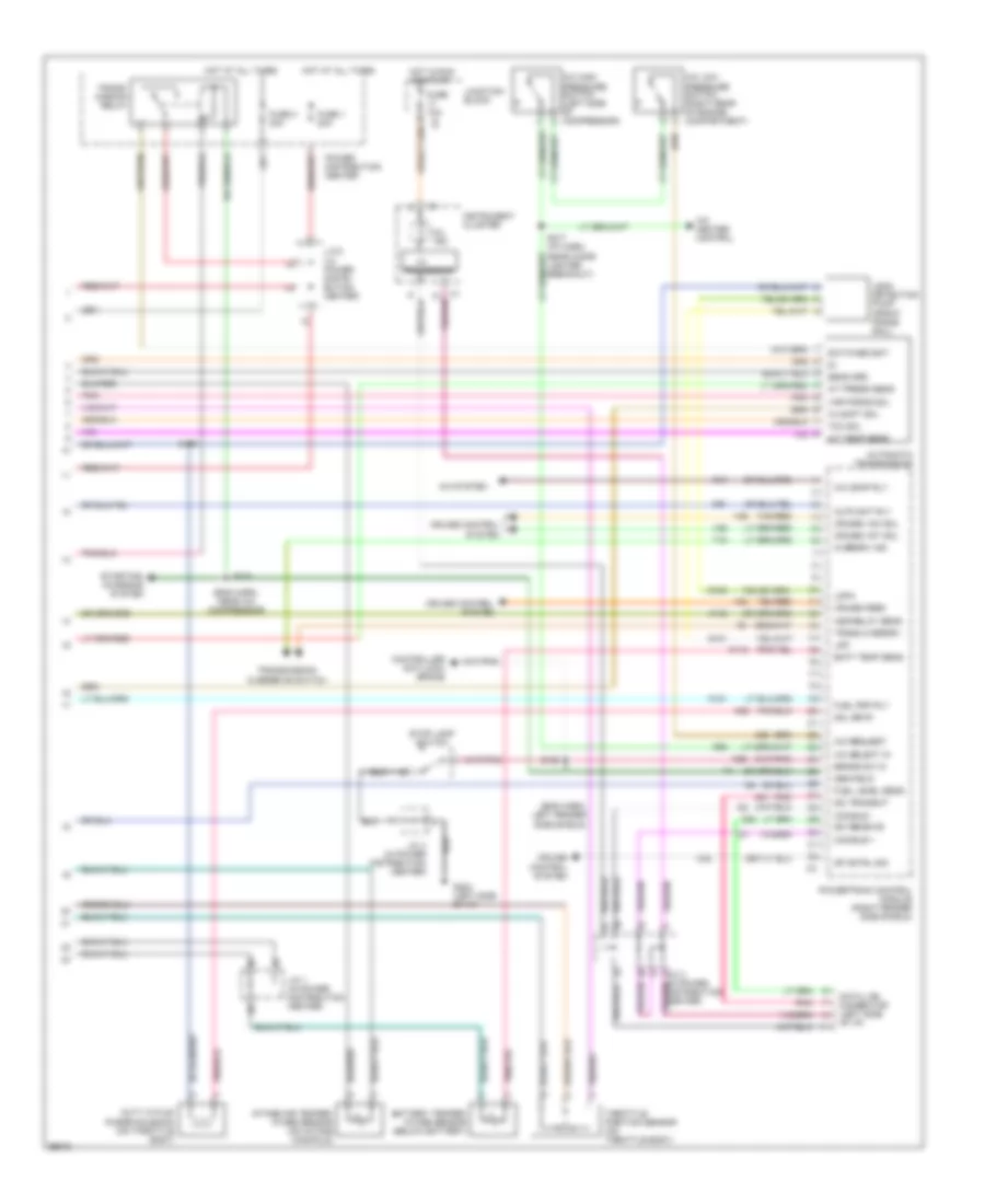
5.9L, Engine Performance Wiring Diagrams (3 of 3) for Dodge Dakota R/T 1998
List of elements for 5.9L, Engine Performance Wiring Diagrams (3 of 3) for Dodge Dakota R/T 1998:
- (eng harn, left fender side shield)
- (eng harn, near a/c compressor)
- 3-4 shft sol
- A/c comp rly
- A/c heater control
- A/c high pressure switch (left side of compressor)
- A/c low pressure switch (right rear of engine compartment)
- A/c request
- A/c select in
- A/c system
- A/t press sens
- A/t temp sens
- A142
- Asd relay sens
- Auto sht rly
- Automatic transmission
- Batt temp sens
- Battery temper- ature sensor (below battery)
- Brake sw in
- C13
- C20
- C32
- C90
- Ccd bus +
- Ccd bus -
- Controller anti-lock brake
- Cruise control system
- Cruise feed
- Cruise vac sol
- Cruise vnt sol
- D20
- D21
- Data link connector (left side of i/p)
- Distribution center)
- Duty cycle/ purge solenoid (on throttle body)
- Fuel level sens
- Fuel pmp rly
- Fuse 1 20a
- Fuse 10a
- Fuse 3 30a
- G100
- G101
- G202 (left side of i/p)
- Gen field
- Hot at all times
- Hot in run or start
- I/o
- Instrument cluster
- Intake air temper- ature sensor (on intake manifold)
- J/c 1 (in power distribution center)
- J/c 2 (in power distri- bution center)
- J/c 3 (in power
- J/c 4 (in power distribution center)
- Junction block
- K118
- K151
- K29
- K51
- K52
- Ldp
- Ldpa
- Leak detection pump (front frame rail)
- Mil ind.
- Overdrv ind
- Pnk
- Power distribution center
- Powertrain control module (right fender side shield)
- Processor
- S104
- S129
- S158
- S217 (i/p harn, near cigar lighter breakout)
- Sci receive
- Sci transmit
- Sens grd
- Sol drvr
- Sp cntrl sig
- Starting/ charging system
- Stop lamp switch
- Switched bat
- T18
- Tan/red
- Tcc sol
- Throttle position sensor (on throttle body)
- Trans overdrv
- Trans- mission relay
- Transmission overdrive switch
- V32
- V35
- V36
- Var force sol