ENGINE PERFORMANCE
4.7L
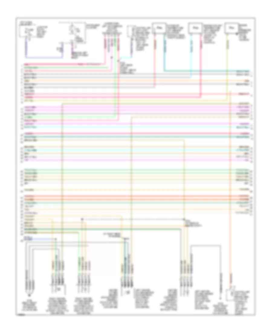
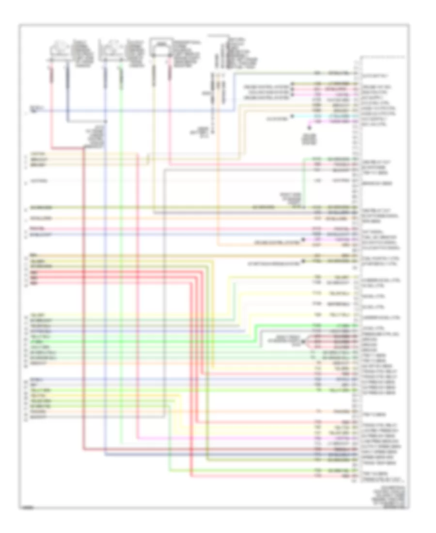
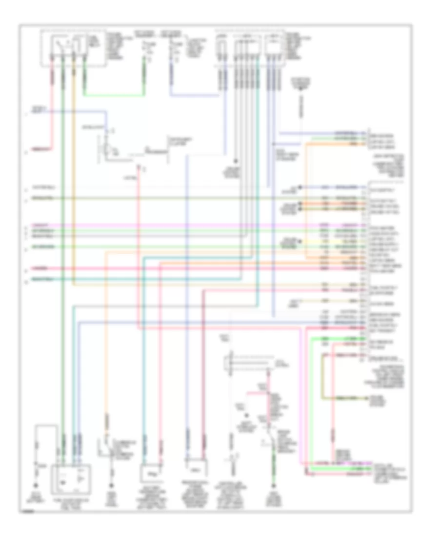
4.7L, Engine Performance Wiring Diagram (1 of 6) for Dodge Durango R/T 2003

List of elements for 4.7L, Engine Performance Wiring Diagram (1 of 6) for Dodge Durango R/T 2003:
- (behind right side of dash) s202
- (right front of engine compt) g100
- (right rear of engine compt)
- A/c pres sig
- A/c pressure transducer (on discharge line, near a/c compressor)
- A/c sig
- A14
- A169
- Amb temp sens
- C18
- Cam pos sns
- Camshaft position sensor (on front of right cyl head)
- Cmp sig
- Coil driver 1
- Coil driver 2
- Coil driver 3
- Coil driver 4
- Coil driver 5
- Coil driver 6
- Coil driver 7
- Coil driver 8
- Computer data lines system
- Cps sig
- Crankshaft position sensor (on right rear side of cyl block)
- Crnk pos sns
- D15
- D20
- D21
- D25
- Ect sens in
- F11
- F18
- Fuse 10a
- Fuse 20a
- Fused b(+)
- G31
- G60
- Gen field
- Ground
- Ho2s 1/1 htr
- Ho2s 1/1 sig
- Ho2s 1/2 sig
- Ho2s 2/1 htr
- Ho2s 2/1 sig
- Ho2s 2/2 sig
- Ho2s return
- Hot at all times
- Hot at start
- Hot in run or start
- Iac mtr cntrl
- Iac return
- Iat sens in
- Idle air control motor (on left side of throttle body)
- Ign power
- Inj 1 driver
- Inj 2 driver
- Inj 3 driver
- Inj 4 driver
- Inj 5 driver
- Inj 6 driver
- Inj 7 driver
- Inj 8 driver
- J/c 2
- Junction block (on left end of dash)
- K11
- K12
- K13
- K14
- K141
- K199
- K20
- K21
- K22
- K24
- K241
- K26
- K28
- K341
- K38
- K39
- K41
- K44
- K58
- K60
- K902
- K904
- K91
- K92
- K93
- K94
- K95
- K96
- K97
- K98
- K99
- Map sens in
- Oil pres sig
- Pci bus
- Pnk
- Power distribution center (on left front inner fender panel)
- Powertrain control module (on right front inner fender, forward of washer fluid reservoir)
- S101 (right rear of engine compt)
- S102
- S107 (rear of engine)
- Sci receive
- Sci transmit
- Sens gnd
- Sensor gnd
- Starting/ charging system
- Tan
- Tan/pnk
- Tan/red
- Tps sens in
- Vss
- Z12
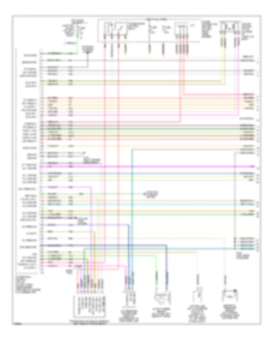
4.7L, Engine Performance Wiring Diagram (2 of 6) for Dodge Durango R/T 2003
List of elements for 4.7L, Engine Performance Wiring Diagram (2 of 6) for Dodge Durango R/T 2003:
- (at right rear of engine)
- (behind left side of dash) s201
- (under dash, left of steering column) data link connector (dlc)
- Controller anti-lock brake (abs) (on top of hydraulic control unit, at c1
- Controller anti-lock brake (abs) (on top of hydraulic control unit, at left rear of eng compt)
- Engine coolant temperature (ect) sensor (in water jacket, at front of intake manifold)
- Engine oil pressure sensor (on oil filter housing)
- Fuse 10a
- G105 (right front of engine, top rear of valve cover)
- Heated oxygen sensor (downstream) (federal) (on outlet end of catalytic converter)
- Heated oxygen sensor (upstream) (federal) (near right side of trans- mission, in exhaust pipe)
- Hot in run or start
- I/o proc- essor
- Instrument cluster
- Intake air temperature (iat) sensor (on intake manifold, near throttle body)
- Junction block (on left end of dash)
- Left heated oxygen sensor (downstream) (california) (on outlet end of left catalytic converter)
- Left heated oxygen sensor (upstream) (california) (on inlet end of left catalytic converter)
- Left rear of eng compt)
- Mil ind
- Nca
- Pnk
- Right heated oxygen sensor (downstream) (calfornia only) (on outlet end of right catalytic converter)
- Right heated oxygen sensor (upstream) (california only) (on inlet end of right catalytic converter)
- S104 (at rear of engine compt)
- S105
- S124 (left rear of eng compt, above wheelwell)
- Sci rec
- Tan
- Tan/pnk
- Tan/red
- Vss
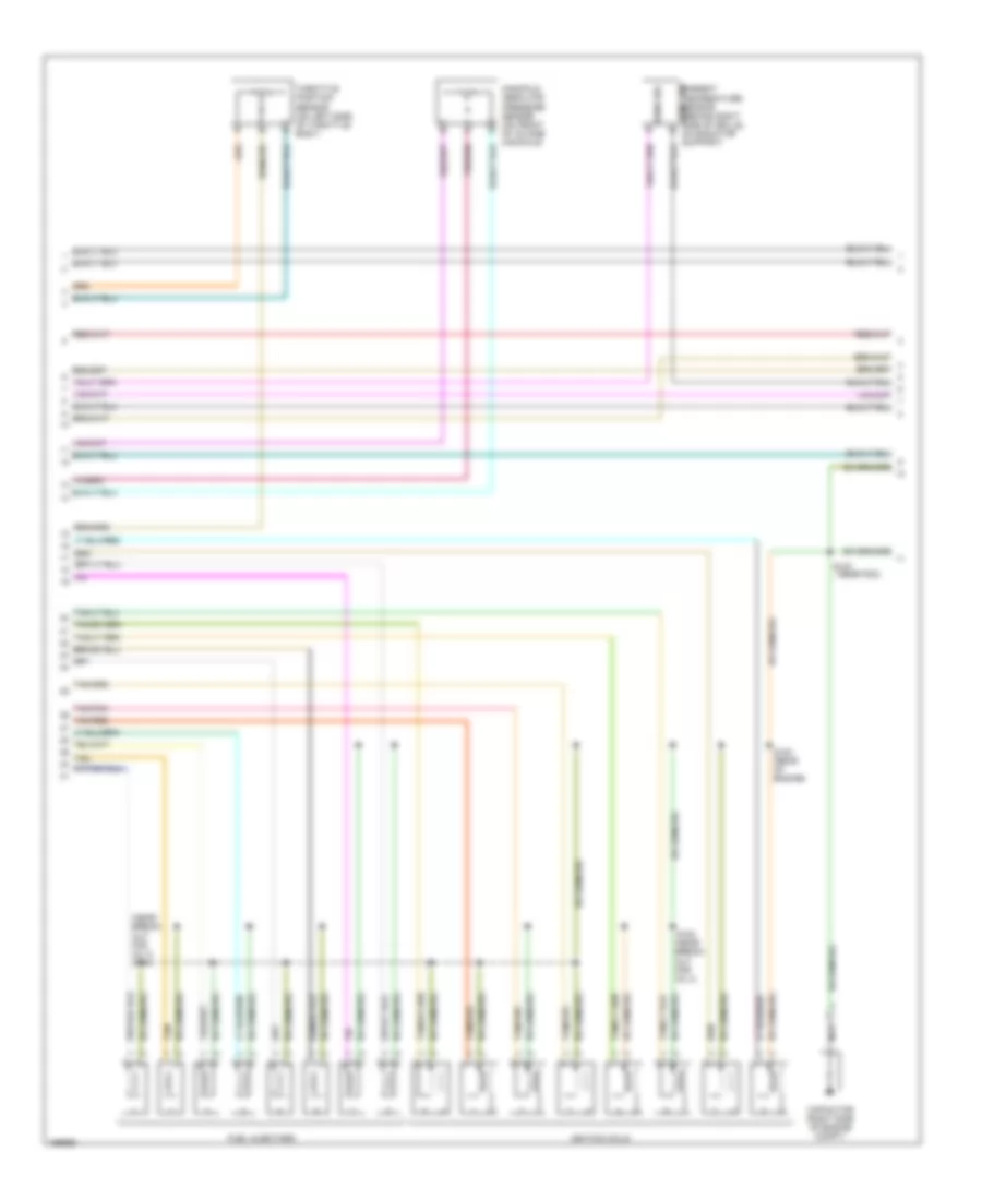
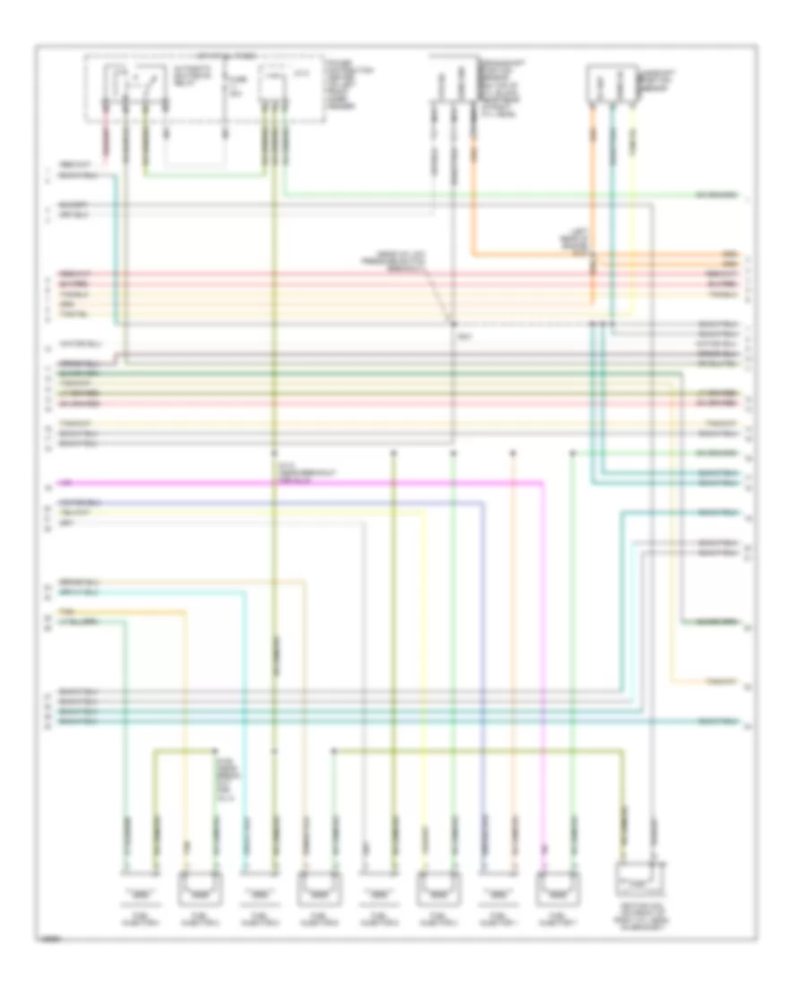
4.7L, Engine Performance Wiring Diagram (3 of 6) for Dodge Durango R/T 2003
List of elements for 4.7L, Engine Performance Wiring Diagram (3 of 6) for Dodge Durango R/T 2003:
- (near break- out for inj 3) s134
- (near pdc)
- Ambient temperature sensor (behind right side of grille, sens gnd on radiator support)
- Capacitor (right side of engine compt)
- Fuel injectors
- Ignition coils
- Manifold absolute pressure sensor (on front of intake) manifold)
- Nca
- S183 (near break- out for inj 4)
- S184 (rear of engine)
- S187
- Sens sig
- Tan
- Tan/pnk
- Tan/red
- Throttle position sensor (on left side of throttle body)
4.7L, Engine Performance Wiring Diagram (4 of 6) for Dodge Durango R/T 2003
List of elements for 4.7L, Engine Performance Wiring Diagram (4 of 6) for Dodge Durango R/T 2003:
- (near diagnostic junction port breakout) s206
- Battery temperature sensor (under battery, attached to battery tray)
- Brake lamp switch (on brake pedal bracket)
- Controller anti-lock brake (abs) (on top of hydraulic control unit, at left rear of eng compt)
- Cruise control system
- Fuel pump module (at fuel pump)
- Fuel pump relay
- Fuse 10a
- Fuse f 20a
- G113 (near battery)
- G207 (lower center of dash)
- G208 (at left kick panel)
- Hot at all times
- Hot in run or start
- J/c 2 (in pdc)
- J/c 3
- Junction block (on left end of dash)
- Overdrive switch
- Power distribution center (on left front inner fender panel)
- Red
- S306
- Sensor
- Shift interlock system
- Transmission control relay
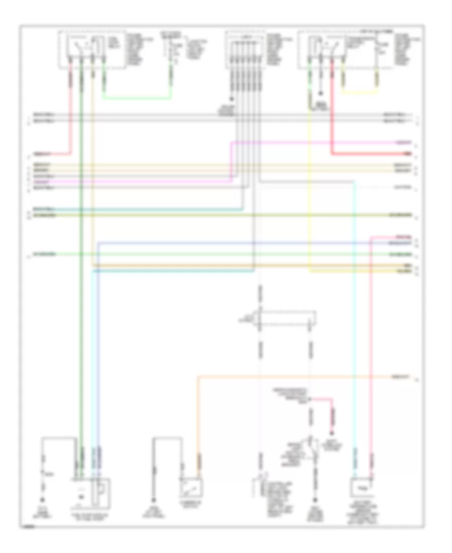
4.7L, Engine Performance Wiring Diagram (5 of 6) for Dodge Durango R/T 2003
List of elements for 4.7L, Engine Performance Wiring Diagram (5 of 6) for Dodge Durango R/T 2003:
- (left rear of engine)
- 2-4 press
- 2c sol ctrl
- 4c prs sw sens
- 4c sol ctrl
- Automatic shut down relay
- Fuse 30a
- G105 (right front of engine, top rear of valve cover)
- Hot at all times
- J/c 2
- L/r press
- Line pressure sensor (on right side of transmission)
- Lr sol ctrl
- Ms sol ctrl
- Od press
- Od sol ctrl
- Power distribution center (on left front inner fender panel)
- Power steering pressure switch (in power steering high pressure line, near steering pump)
- Red
- S103
- S175 (in transmission control module breakout, near pcm)
- Sens gnd
- Sens signal
- Temp sens
- Tran ctrl rly out
- Transmission solenoid/trs assembly (left side of transmission)
- Trs t1 sens
- Trs t2 sens
- Trs t3 sens
- Trs t41 sens
- Trs t42 sens
- Ud press
- Ud sol ctrl
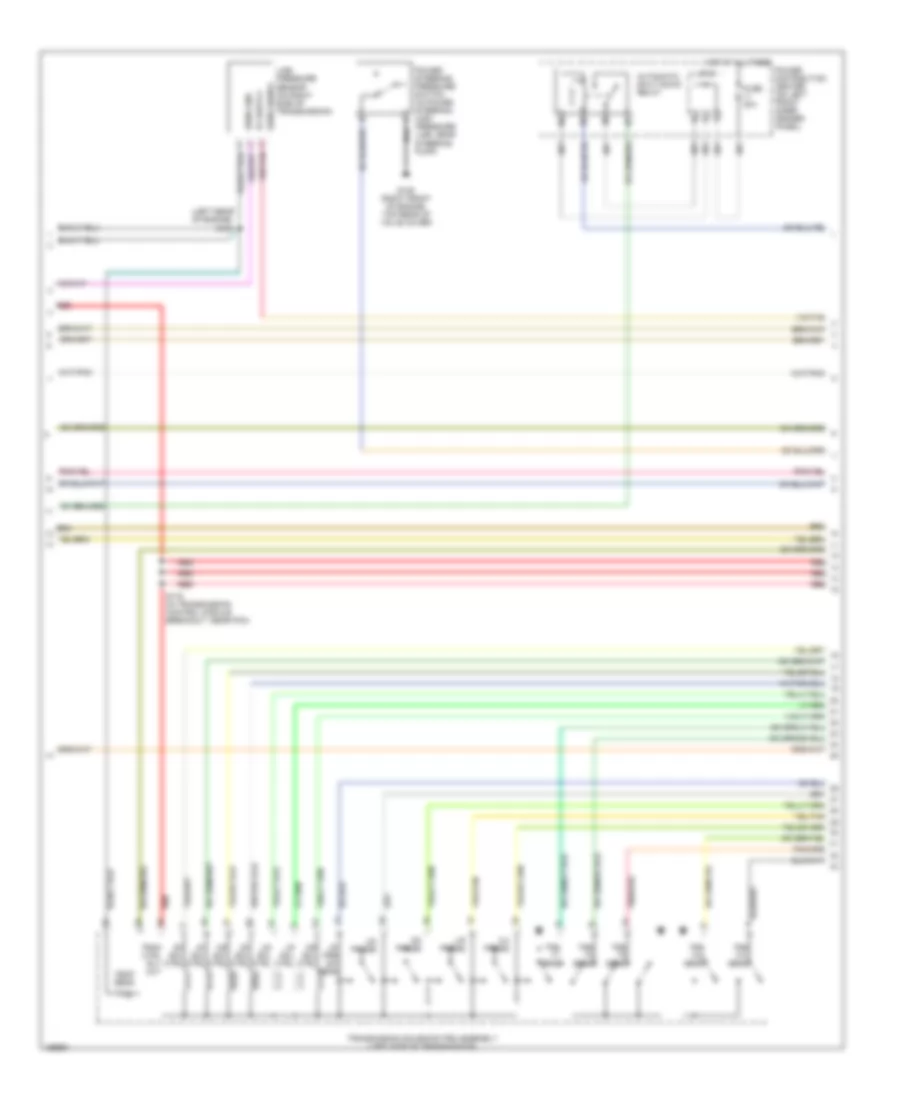
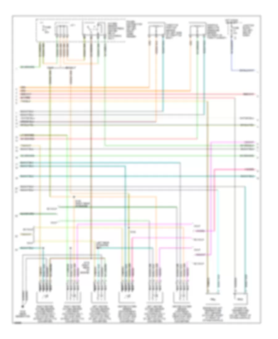
4.7L, Engine Performance Wiring Diagram (6 of 6) for Dodge Durango R/T 2003
List of elements for 4.7L, Engine Performance Wiring Diagram (6 of 6) for Dodge Durango R/T 2003:
- (near battery) g113
- (right front of engine compt) g100
- (right side of engine compt) s176
- 2c pres sw sens
- 2c sol ctrl
- 4c pres sw sens
- 4c sol ctrl
- A/c comp rly
- A/c system
- A142
- Aat signal
- Asd relay out
- Auto sht rly
- Brake sw sens
- C13
- C24
- Cooling fans system
- Cruise control system
- Cruise vnt sol
- Evap purge signal
- Evap/purge
- Fuel lev sens sig
- Fuel pump rly ctrl
- Ground
- Ho2s 1/2 htr ctrl
- Ho2s 2/2 htr ctrl
- Input speed sens
- Input speed sensor (on front left side of trans- mission)
- K10
- K106
- K107
- K118
- K226
- K299
- K31
- K399
- K51
- K52
- K70
- Line pres sens sig
- Low/rev press sw
- Lr sol ctrl
- Ms sol ctrl
- Natural vacuum leak detection assembly (on left frame rail, forward of fuel tank)
- Nvld sol cntl
- Nvld sol ctrl
- Nvld switch
- Nvld switch signal
- Od off sw sens
- Od pres sw sens
- Output speed sens
- Output speed sensor (on left side of trans- mission)
- Overdrive sol ctrl
- Powertrain control module (on right inner fender, forward of washer fluid reservoir)
- Pressure ctrl sol
- Proportional purge solenoid (left rear of engine compt, near brake booster)
- Rad fan ctrl
- Red
- S/c switch signal
- S/c vac ctrl
- S178 (in trans- mission control module breakout)
- S306
- Speed sens gnd
- Sps sens
- Starter rly ctrl
- Starting/charging system
- T118
- T119 t119
- T120
- T13
- T14
- T140
- T15
- T159
- T16
- T29
- T38
- T41
- T42
- T47
- T48
- T50
- T52
- T54
- T59
- T60
- T752
- Trans ctrl relay
- Trans ctrl rly out
- Trans temp sens
- Trs t1 sens
- Trs t2 sens
- Trs t3 sens
- Trs t41 sens
- Trs t42 sens
- Ud pres sw sens
- Undrdrive sol ctrl
- V32
- V35
- V36
- V37
- V40
- Z13
5.9L
5.9L, Engine Performance Wiring Diagram (1 of 4) for Dodge Durango R/T 2003
List of elements for 5.9L, Engine Performance Wiring Diagram (1 of 4) for Dodge Durango R/T 2003:
- (near pcm)
- 3-4 shift
- A/c pres sig
- A/c pressure transducer (near a/c compressor, on discharge line)
- A/c sig
- A/t temp sig
- A14
- C18
- C24
- Cam pos sns
- Coil driver
- Controller anti-lock brake (on top of hydraulic control unit), at left rear of eng compt)
- Cooling fans system
- Crnk pos sns
- Ect sens in
- Engine oil pressure sensor (on top rear of engine, near distributor)
- F18
- Fuse 10a
- Fuse 20a
- Fuse f 20a
- Fused b(+)
- G115 (right fender side shield)
- G60
- Gen field
- Gov pres cntl
- Gov pres sig
- Ground
- Ho2s 1/1 sig
- Ho2s 1/2 sig
- Ho2s 2/1 sig
- Ho2s 2/2 sig
- Hot at all times
- Hot in run or start
- Iat sens in
- Idle air 1
- Idle air 2
- Idle air 3
- Idle air 4
- Idle air control motor (on rear of throttle body)
- Ign power
- Inj 1 driver
- Inj 2 driver
- Inj 3 driver
- Inj 4 driver
- Inj 5 driver
- Inj 6 driver
- Inj 7 driver
- Inj 8 driver
- J/c 1
- Junction block (on left end of dash)
- K11
- K12
- K13
- K14
- K141
- K19
- K20
- K21
- K22
- K24
- K241
- K26
- K28
- K30
- K341
- K38
- K39
- K40
- K41
- K44
- K54
- K58
- K59
- K60
- K88
- Map sens in
- Od sol cntl
- Oil pres sig
- Out spd sig
- Output speed sensor (on lower left rear of trans)
- P/n signal
- Pnk
- Power distribution center (on left front inner fender)
- Powertrain control module (on left front inner fender, forward of washer fluid reservoir)
- Rad fan ctrl
- Red
- S103 (left rear of engine)
- S135
- Sens gnd
- Sensor gnd
- Spd sens gnd
- Starting/ charging system
- T13
- T14
- T25
- T34
- T41
- T60
- Tan
- Tcc sol cntl
- Tps sens in
- Trans rly cntl
- Trans rly out
- Transmission control relay
- Transmission solenoid assembly (left side of transmission)
- Vss
- Z12
5.9L, Engine Performance Wiring Diagram (2 of 4) for Dodge Durango R/T 2003
List of elements for 5.9L, Engine Performance Wiring Diagram (2 of 4) for Dodge Durango R/T 2003:
- (left rear of engine) s107
- (near a/c low pressure switch breakout)
- 5v sup
- Automatic shutdown relay
- Camshaft position sensor
- Cps sig
- Fuel injector 1
- Fuel injector 2
- Fuel injector 3
- Fuel injector 4
- Fuel injector 5
- Fuel injector 6
- Fuel injector 7
- Fuel injector 8
- Fuse 30a
- Hot at all times
- Ignition coil (on front of right cyl head, on bracket)
- J/c 2
- Nca
- Power distribution center (on left front inner fender)
- S101
- S106 (near break- out for inj 4)
- S110 (near breakout for inj 5)
- Sens gd
- Sens gnd
- Tan
5.9L, Engine Performance Wiring Diagram (3 of 4) for Dodge Durango R/T 2003
List of elements for 5.9L, Engine Performance Wiring Diagram (3 of 4) for Dodge Durango R/T 2003:
- (left rear of engine) s101
- Calif
- Engine coolant temperature (ect) sensor (in water jacket at front of intake manifold)
- Ex calif
- Fuse 10a
- Fuse u 20a
- G105 (near generator)
- Heated oxygen sensor (downstream) (ex california) (on outlet end of catalytic converter)
- Heated oxygen sensor (upstream) (ex california) (near inlet end of catalytic converter)
- Hot in run or start
- Intake air temperature (iat) sensor (on left front of intake manifold)
- J/c 1
- Junction block (on left end of dash)
- Left heated oxygen sensor (downstream) (california only) (on outlet end of left catalytic converter)
- Left heated oxygen sensor (upstream) (california only) (on inlet end of left catalytic converter)
- Manifold absolute pressure sensor (on front of throttle body)
- Nca
- Oxygen sensor downstream heater relay (california only)
- Power distribution center (on left front inner fender)
- Right heated oxygen sensor (downstream) (california only) (on outlet end of right catalytic converter)
- Right heated oxygen sensor (upstream) (california only) (on inlet end of right catalytic converter)
- S122
- S136 (right rear of engine)
- S179 (right rear of engine)
- Throttle position sensor (on left side of throttle body)
5.9L, Engine Performance Wiring Diagram (4 of 4) for Dodge Durango R/T 2003
List of elements for 5.9L, Engine Performance Wiring Diagram (4 of 4) for Dodge Durango R/T 2003:
- (behind center of dash) s201
- (not used)
- A/c comp rly
- A/c sw sens
- A/c system
- A142
- Asd relay out
- Auto sht rly
- Batt temp sens
- Battery temperature sensor (under battery, attached to battery tray)
- Brake lamp switch (on brake pedal bracket)
- Brake sw sens
- C13
- C20
- Controller anti-lock brake (on top of hydraulic control unit, at left rear of eng compt)
- Cruise control system
- Cruise sw sig
- Cruise vac sol
- Cruise vnt sol
- D20
- D21
- D25
- Data link connector (dlc) (under dash, left of steering column)
- Evap/purge
- Fuel pump module (on top of fuel tank)
- Fuel pump relay
- Fuel pump rly
- Fuse 10a
- G113 (near battery)
- G207 (lower center of dash)
- G208 (left kick panel)
- Gen source
- Ho2s dwn cntl
- Hot in run or start
- I/o processor
- Instrument cluster
- J/c 1
- J/c 2
- J/c 2 (in pdc)
- J/c 3
- Junction block (on left end of dash)
- K100
- K106
- K107
- K118
- K125
- K200
- K226
- K31
- K51
- K512
- K52
- Ldp sol cntl
- Ldp sw sens
- Leak detection pump (under battery tray & power distribution center)
- Mil ind
- Od off sw
- Overdrive switch (on steering column)
- Pci bus
- Pnk
- Power distribution center (on left front inner fender)
- Powertrain control module (on left front inner fender, forward of washer fluid reservoir)
- Proportional purge solenoid (left rear of engine compt, near brake booster)
- Pwm heater
- S123 (right rear of engine)
- S206 (near diag junction port break- out)
- S306
- Sci receive
- Sci transmit
- Sensor
- Shift interlock system
- Starting/ charging system
- Tan/red
- V32
- V35
- V36
- V37
- V40