AIR CONDITIONING
Automatic A/C Wiring Diagram (1 of 2) for Buick Park Avenue 1999

List of elements for Automatic A/C Wiring Diagram (1 of 2) for Buick Park Avenue 1999:
- (eng harn, 6 cm from cruise control module breakout)
- (i/p harn, behind right side of dash)
- (right kick panel) g203
- +5v
- A10
- A11
- A12
- Act enable
- Act sense
- Amb temp input
- Ambient temperature sensor (center front of eng compt)
- B10
- B11
- B12
- Battery
- Blo mot maxi fuse 30a
- Blo spd input
- Blower control module (behind right side of dash)
- Blower ground
- Blower motor
- Blower spd ctrl
- C10
- C11
- C12
- C13
- C14
- C15
- C16
- Clock driver
- Cstr/ sbm fuse 10a
- D10
- D11
- D12
- D13
- D14
- D15
- D16
- Data line
- Data link connector (left side of dash)
- Flange ground
- G200 (left kick panel)
- Ground
- Heater & a/c control
- Heater and a/c programmer (behind right side of dash)
- Hot at all times
- Hot in start or run
- Hvac fuse 10a
- I/p junction block
- Ignition
- Inside air temperature sensor (in left knee bolster, right of steering column)
- Inside temp input
- Interior lights system
- Kdd
- Kdd c/k
- Lamp feed
- Left a/c temperature sensor (on dash, behind left center a/c vent)
- Left heater temperature sensor (above left sound insulator)
- Left sunload temperature sensor (behind left side of dash)
- Lt a/c sensor
- Lt htr sensor
- Lt solar sensor
- Pass ctrl gnd
- Pass ctrl input
- Passenger climate control
- Pwm blw spd ctrl
- Red
- Right a/c temperature sensor (on dash, behind right center a/c vent)
- Right heater temperature sensor (above right sound insulator)
- Right sunload temperature sensor (top right of dash)
- Rt a/c sensor
- Rt htr sensor
- Rt solar sensor
- S208
- S213 (i/p harn, 6.5 cm from passenger heater and a/c programmer connector)
- S214
- Sensor ground
- Signal driver
- Sound system
- Tan
- Underhood junction block
- Vf input
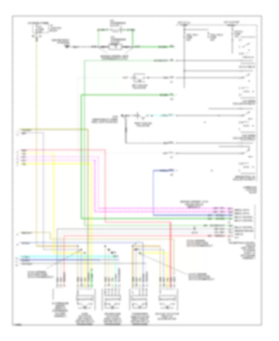
Automatic A/C Wiring Diagram (2 of 2) for Buick Park Avenue 1999
List of elements for Automatic A/C Wiring Diagram (2 of 2) for Buick Park Avenue 1999:
- (center front of engine)
- (engine harness, 15 cm cruise module breakout)
- (engine harness, near compressor clutch)
- (hvac harness, 29 cm from mode actuator breakout)
- (hvac harness, 33.5 cm from mode actuator breakout)
- (hvac harness, 50.5 cm from mode actuator breakout)
- +5 v
- A/c clu fuse 10a
- A/c clu relay
- A/c compressor clutch
- A/c compressor clutch diode
- A/c fuse 10a
- A/c pressure sensor (near a/c compressor, on hose assembly)
- A10
- Air inlet actuator (right of blower motor)
- Cool fan 1 fuse 30a
- Cool fan 2 fuse 30a
- D11
- Driver's side actuator (right side of heater and a/c programmer)
- E10
- F11
- G105 (near base of under- hood junction block)
- G125
- High speed cooling fan relay
- Hot at all times
- Hot in start
- I/p junction block
- Left cooling fan motor
- Low speed cooling fan relay
- Mode actuator (left side of heater and a/c programmer)
- Nca
- Or run
- Passenger's side actuator (right side of heater and a/c programmer)
- Powertrain control module (left front of engine compt, in air cleaner assembly)
- Red
- Relay control
- Right cooling fan motor
- S106
- S107
- S115
- S274
- S275
- S278
- Sensor ground
- Serial data
- Series/parallel cooling fan relay
- Solid state
- Underhood jucntion block
- Vsb a/c
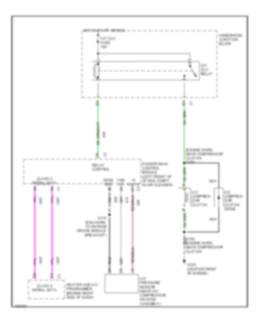
Compressor Wiring Diagram for Buick Park Avenue 1999
List of elements for Compressor Wiring Diagram for Buick Park Avenue 1999:
- (engine harn, near compressor clutch)
- (engine harn, near compressor clutch) s107
- +5 volts
- A/c clu relay
- A/c clu fuse 10a
- A/c compres- sor clutch
- A/c compres- sor clutch diode
- A/c pressure sensor (near a/c compressor, on hose assembly)
- Class 2 serial data
- G125 (center front of engine)
- Heater and a/c programmer (behind right side of dash)
- Hot in start or run
- Nca
- Powertrain control module (left front of of eng compt, in air cleaner)
- Relay control
- S115 (eng harn, 15 cm from cruise module breakout)
- Sens grd
- Underhood junction block
- Vsb a/c