AIR CONDITIONING
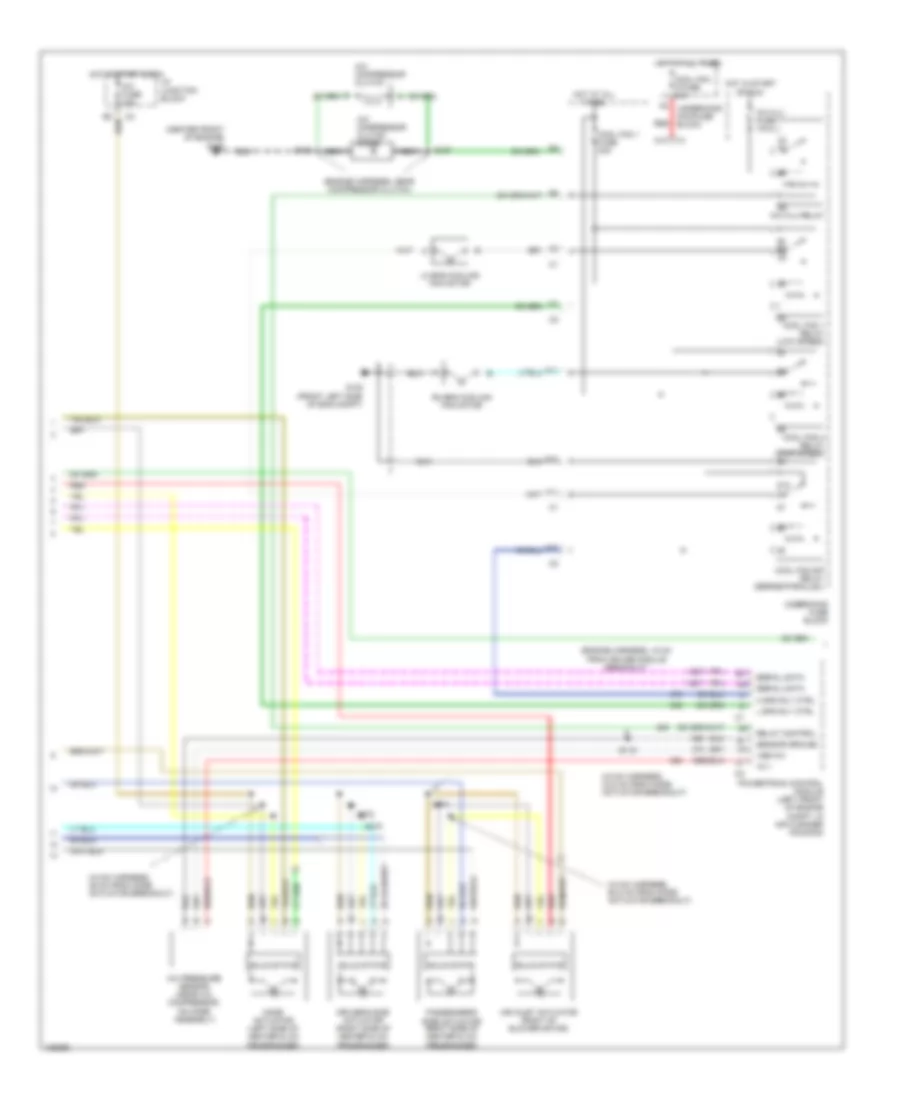
Automatic A/C Wiring Diagram (1 of 3) for Buick Park Avenue Ultra 2000

List of elements for Automatic A/C Wiring Diagram (1 of 3) for Buick Park Avenue Ultra 2000:
- (eng harn, 6 cm from cruise control module breakout)
- (i/p harn, behind right side of dash)
- (right kick panel) g203
- +5v
- A10
- A11
- A12
- Act sense
- Air in act ctrl
- Amb temp input
- Ambient air temperature sensor (center front of eng compt)
- B10
- B11
- B12
- Battery
- Blo mot fuse 30a
- Blo spd input
- Blower control module (behind right side of dash)
- Blower motor
- Blower spd ctrl
- C10
- C11
- C12
- C13
- C14
- C15
- C16
- Clock driver
- Control ground
- Cstr/ sbm fuse 10a
- D10
- D11
- D12
- D13
- D14
- D15
- D16
- Data line
- G200 (left kick panel)
- Ground
- Ground dist system
- Heater & a/c control
- Heater & a/c programmer (behind right side of dash)
- Hot at all times
- Hot in start or run
- Hvac fuse 10a
- I/p junction block
- Ignition
- Inside air temperature sensor (under left side of dash, near left center a/c vent)
- Inside temp input
- Interior lights system
- Kdd
- Kdd c/k
- L temp act ctrl
- Lamp feed
- Left a/c temperature sensor (on dash, behind left center a/c vent)
- Left panel temperature sensor (left side of dash, near a/c vent)
- Left pnl temp sig
- Left sunload temperature sensor (behind left side of dash)
- Lt htr sensor
- Lt solar sensor
- Mode act ctrl
- Motor ground
- Pas temp ctrl sig
- Passenger climate control
- Pwm blw spd ctrl
- R temp act ctrl
- Red
- Right a/c temperature sensor (on dash, behind right center a/c vent)
- Right panel temperature sensor (right side of dash, near a/c vent)
- Right pnl temp sig
- Right sunload temperature sensor (top right of dash)
- Rt htr sensor
- Rt solar sensor
- S208
- S213 (i/p harn, 44 cm from hvac control assembly)
- S214
- Sensor ground
- Signal driver
- Sound system
- Speed cont grd
- Tan
- Underhood junction block
- Vf input
Automatic A/C Wiring Diagram (2 of 3) for Buick Park Avenue Ultra 2000
List of elements for Automatic A/C Wiring Diagram (2 of 3) for Buick Park Avenue Ultra 2000:
- (center front of engine)
- (engine harness, 15 cm from cruise module breakout)
- (engine harness, near compressor clutch)
- (hvac harness, 29 cm from mode actuator breakout)
- (hvac harness, 33.5 cm from mode actuator breakout)
- (hvac harness, 50.5 cm from mode actuator breakout)
- +5 v
- 87a
- A/c clu fuse 10a
- A/c clu relay
- A/c compressor clutch
- A/c compressor clutch diode
- A/c fuse 10a
- A/c pressure sensor (near a/c compressor, on hose assembly)
- A10
- Air inlet actuator (right of blower motor)
- Cool fan 1 fuse 30a
- Cool fan 1 relay (low speed)
- Cool fan 2 fuse 30a
- Cool fan 2 relay (high speed)
- Cool fan s/p relay (series/parallel)
- D11
- Driver's side actuator (right side of heater & a/c programmer)
- E10
- F11
- G100 (front left side of eng compt)
- G125
- H spd rly ctrl
- Hot at all times
- Hot in start
- Hot in start & run
- I/p junction block
- L spd rly ctrl
- Lh eng cooling fan motor
- Mode actuator (left side of heater & a/c programmer)
- Nca
- Or run
- Passenger's side actuator (right side of heater & a/c programmer)
- Powertrain control module (left front of engine compt, in air cleaner housing)
- Red
- Relay control
- Rh eng cooling fan motor
- S106
- S107
- S115
- S274
- S275
- S278
- Sensor ground
- Serial data
- Solid state
- Underhood fuse block
- Vsb a/c
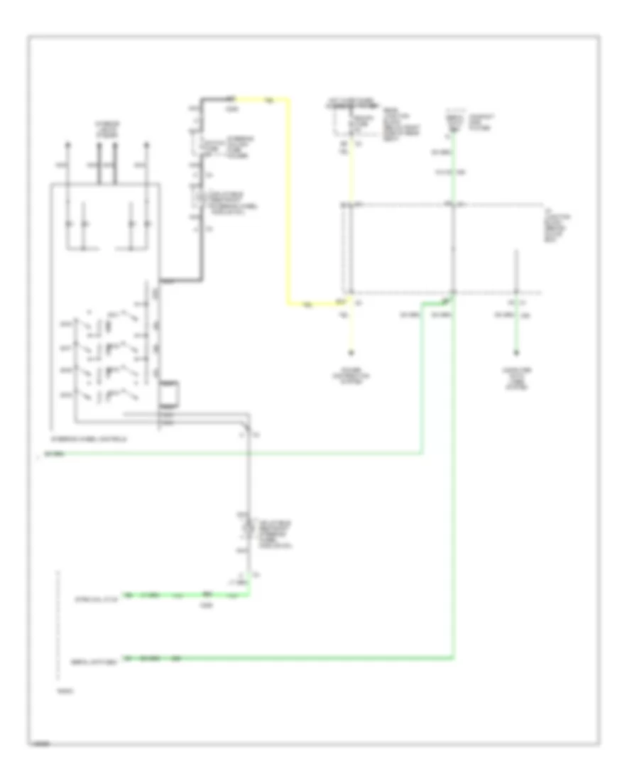
Automatic A/C Wiring Diagram (3 of 3) for Buick Park Avenue Ultra 2000
List of elements for Automatic A/C Wiring Diagram (3 of 3) for Buick Park Avenue Ultra 2000:
- A10
- B10
- B12
- C1 f5
- C206
- Compact disc player
- Computer data lines system
- F8 c4
- Hot in retained accessory power
- I/p junction block (behind glove box)
- Inflatable restraint steering wheel module coil
- Interior lights system
- Nca
- Power distribution system
- Radio
- Rdo/ph fuse 5a
- Rear junction block (below right side of rear seat)
- Serial data e&c
- Steering column fuse holder
- Steering wheel controls
- Strg whl ctlr
- Sw1
- Sw2
- Sw3
- Sw4
- Sw5
- Sw6
- Sw7
- Sw8
- Switch fuse 2a
- W/u1s
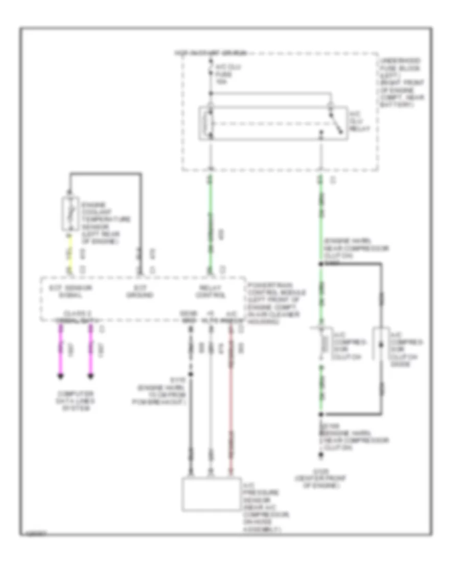
Compressor Wiring Diagram for Buick Park Avenue Ultra 2000
List of elements for Compressor Wiring Diagram for Buick Park Avenue Ultra 2000:
- (engine harn, near compressor clutch)
- (engine harn, near compressor clutch) s107
- +5 vlts
- A/c clu relay
- A/c clu fuse 10a
- A/c compres- sor clutch
- A/c compres- sor clutch diode
- A/c press
- A/c pressure sensor (near a/c compressor, on hose assembly)
- Class 2 serial data
- Computer data lines system
- Ect
- Ect sensor signal
- Engine coolant temperature sensor (left rear of engine)
- G125 (center front of engine)
- Ground
- Hot in start or run
- Nca
- Powertrain control module (left front of engine compt, in air cleaner housing)
- Relay control
- S115 (engine harn, 15 cm from pcm breakout)
- Sens grd
- Underhood fuse block (left) (right front of engine compt, near battery)