INSTRUMENT CLUSTER
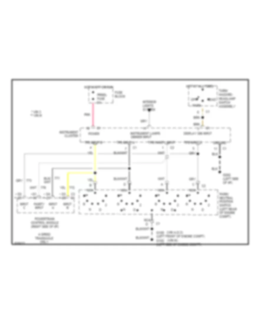
Electronic PRNDL Wiring Diagram, with Console for Buick Skylark Limited 1994

List of elements for Electronic PRNDL Wiring Diagram, with Console for Buick Skylark Limited 1994:
-
- * vin d & 3 ** vin m
- (vin a,d,3)
- (vin m)
- * **
- 4 speed transaxle only
- C3 c1
- D1 * **
- Display dim input
- Electronic prndl control module (center console)
- Fuse block
- G100 (left front of engine compt) g102 (left side of engine compt)
- G202 (left side of i/p)
- Ground
- Head
- Hot at all times
- Hot in off or run
- Input a
- Input b
- Input c
- Instrument lamps dimmer input
- Interior lights system
- Nca
- Off
- Parity input
- Park
- Park/ neutral position switch (left rear of engine compt)
- Pnk
- Power
- Powertrain control module (right side of i/p)
- Prndl fuse 5a
- Tps input a
- Tps input b
- Tps input c
- Tps parity input
- Turn/ hazard- headlamp switch assembly
Electronic PRNDL Wiring Diagram, without Console for Buick Skylark Limited 1994
List of elements for Electronic PRNDL Wiring Diagram, without Console for Buick Skylark Limited 1994:
-
- * vin 3 ** vin m
- (vin a,d,3)
- (vin m)
- * **
- 4 speed transaxle only
- C3 c1
- D1 * **
- Display dim input
- Fuse block
- G100 (left front of engine compt) g102 (left side of engine compt)
- G202 (left side of i/p)
- Ground
- Head
- Hot at all times
- Hot in off or run
- Input a
- Input b
- Input c
- Instrument cluster
- Instrument lamps dimmer input
- Interior lights system
- Nca
- Off
- Parity input
- Park
- Park/ neutral position switch (left rear of engine compt)
- Pnk
- Power
- Powertrain control module (right side of i/p)
- Prndl fuse 5a
- Tps input a
- Tps input b
- Tps input c
- Tps parity input
- Turn/ hazard- headlamp switch assembly
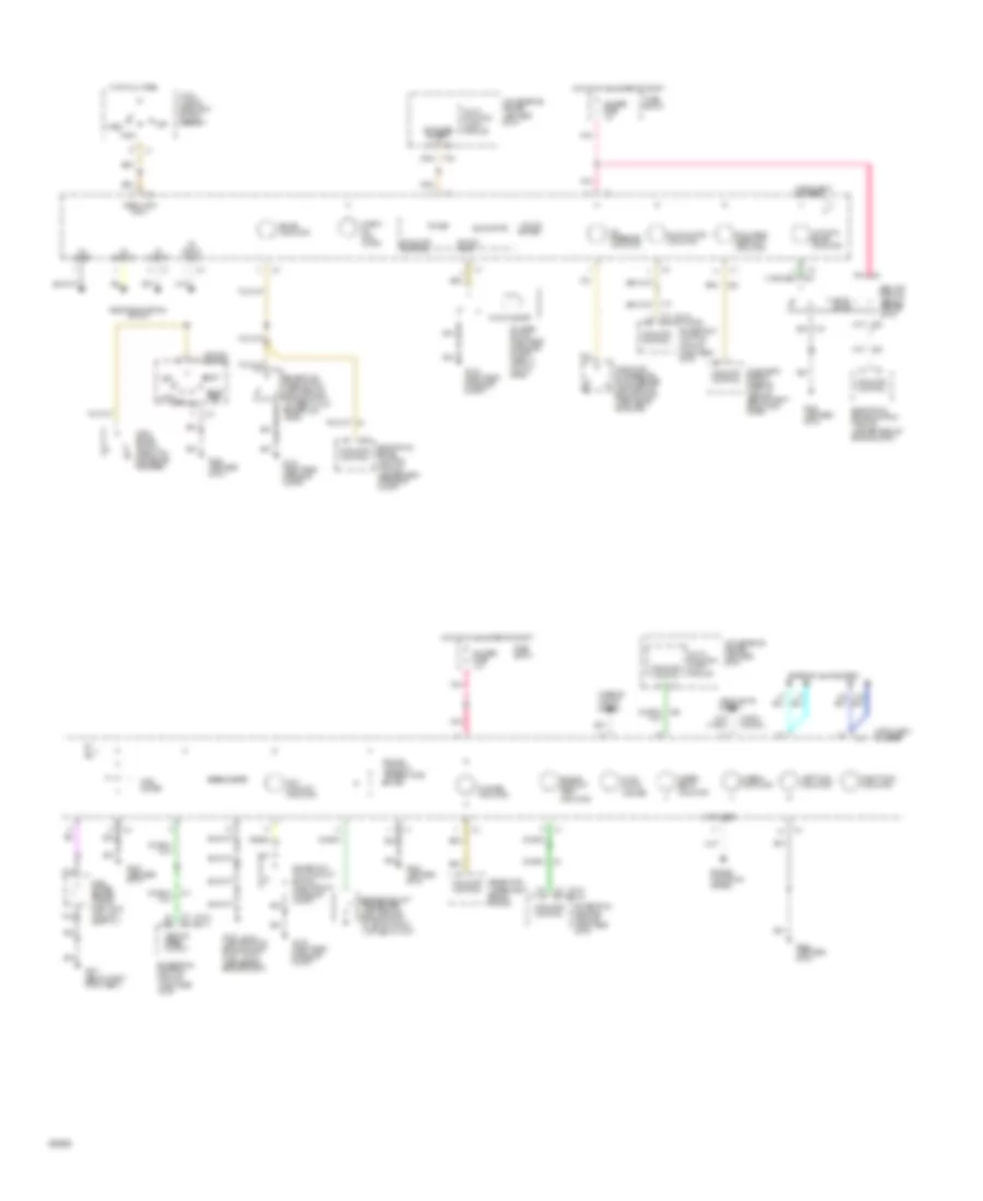
Instrument Cluster Wiring Diagram, Base for Buick Skylark Limited 1994
List of elements for Instrument Cluster Wiring Diagram, Base for Buick Skylark Limited 1994:
-
- (not used)
- (right rear of engine compt)
- (vin 3)
- (vin 3) (vin m)
- (vin m)
- (vin m) (vin 3)
- (vin m) (vin a,d &3)
- (w/ drl) (w/o drl)
- Abs lamp module (behind center of i/p)
- Acc
- Antilock brake indicator
- Brake fluid level switch (left rear of engine compt) (closed w/ low brake fluid level)
- Brake indicator
- Bulb test
- C2 c2
- C2 c3
- C3 c2
- Charge indicator
- Check oil indi- cator
- Convenience center (left side of i/p)
- Diagnostic energy reserve module (behind right front kick panel)
- Display dim input
- Electronic brake control module (center rear of engine compt)
- Electronic prndl circuit
- Engine controls system
- Engine coolant temp sender (left rear of engine compt) (54 @125 c,260 f) (1254 @40 c,100 f)
- Engine coolant temp. indicator
- Engine coolant temperature gauge
- Exterior lights system
- Fasten belts indicator
- Float magnet
- Fuel gauge
- Fuel gauge sender (top of fuel tank) (full-90 ) (empty-0 )
- Fuel pump/ oil pressure switch/sender (left rear of engine compt) (open above 28kpa,4psi)
- Fuse block
- G100 (left front of engine compt) g102 (left side of engine compt)
- G105
- G202 (left side of i/p)
- G301 (below right front seat)
- Gauges fuse 10a
- Generator (upper right side of engine)
- Head
- Headlights system
- Hi beam indicator
- Hot at all times
- Hot in run, bulb test or start
- Ignition switch
- Illum- ination (4 bulbs)
- Indicator control
- Inflatable restraint indicator
- Instrument cluster
- Interior lights system
- Left turn indicator
- Lock
- Low coolant indicator
- Low oil buffer
- Malfunction indicator
- Multi- function alarm module
- Nca
- Off
- Oil level switch (right side of engine compt) (open w/ low oil level)
- Oil pressure indicator
- Park
- Park brake switch (open with park brake released)
- Pnk
- Power
- Powertrain control module (right side of i/p)
- Right turn indicator
- Run
- Solid state
- Speedometer
- Start
- Surge tank low coolant switch (right front of engine compt)
- Switch input
- Switched battery
- Tan
- Tp a input
- Tp b input
- Tp c input
- Tp parity input
- Turn/ hazard headlight switch assembly
- Vehicle speed output
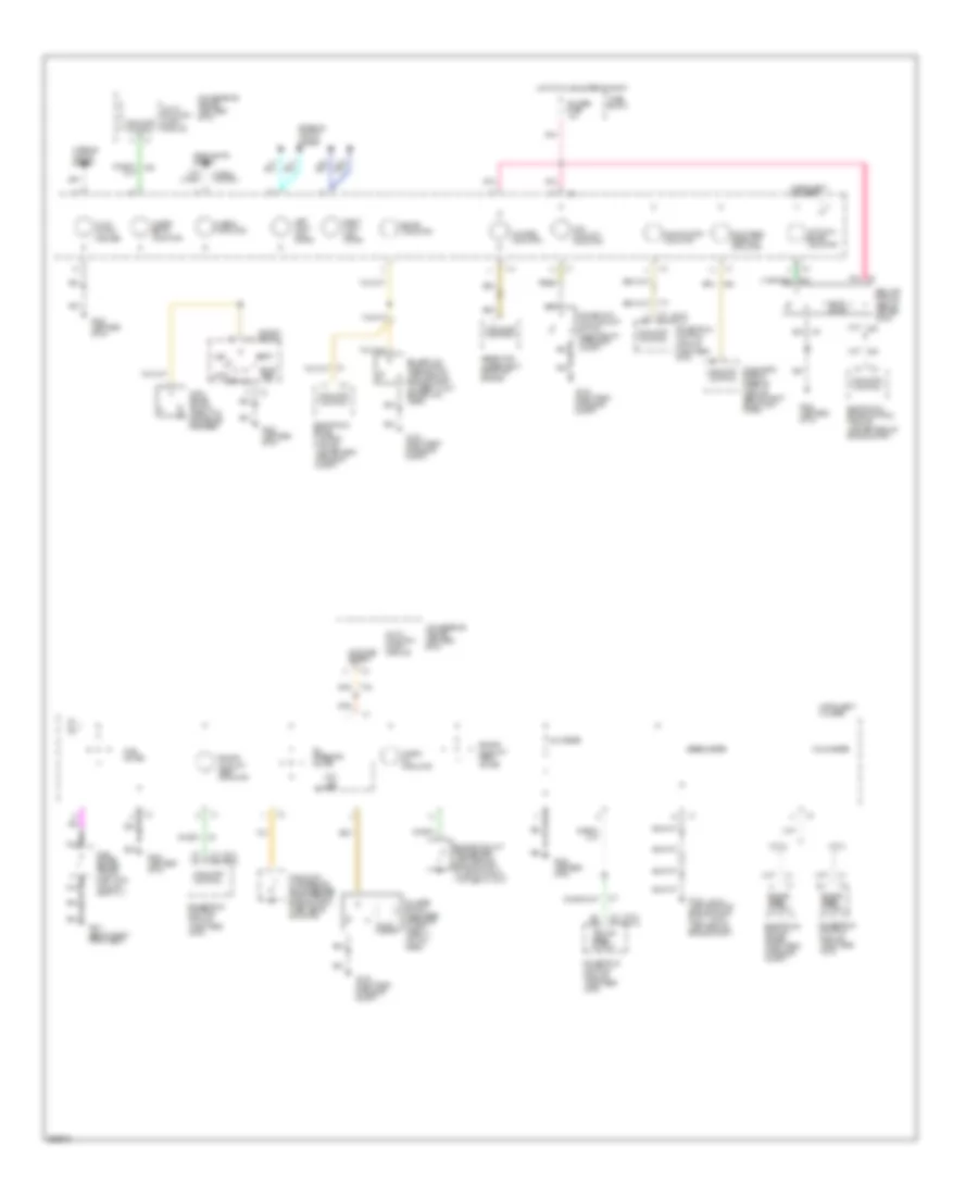
Instrument Cluster Wiring Diagram, Gauges for Buick Skylark Limited 1994
List of elements for Instrument Cluster Wiring Diagram, Gauges for Buick Skylark Limited 1994:
-
- (right rear of engine compt)
- (vin 3)
- (vin 3) (vin m)
- (vin m)
- (vin m) (vin 3)
- (w/ drl) (w/o drl)
- Abs lamp module (behind center of i/p)
- Acc
- Antilock brake indicator
- B11
- Brake fluid level switch (left rear of engine compt) (closed w/ low brake fluid level)
- Brake indicator
- Bulb test
- C2 c2
- C2 c3
- C3 (vin 3) (vin m) c2
- Charge indicator
- Check oil indicator
- Convenience center (left side of i/p)
- Convenience center (left side of i/p)
- Diagnostic energy reserve module (behind right front kick panel)
- Electronic brake control module (center rear of engine compt)
- Electronic ignition system (right rear of engine compt)
- Engine coolant temp sender (left rear of engine compt) (54 @125 c,260 f) (1254 @40 c,100 f)
- Engine coolant temp. gauge
- Engine coolant temp. indicator
- Engine speed output
- Exterior lights system
- Fasten belts indicator
- Float magnet
- Fuel gauge
- Fuel gauge sender (top of fuel tank) (full-90 ) (empty-0 )
- Fuel pump/ oil pressure switch/sender (right rear of engine compt) (open above 28kpa,4psi)
- Fuse block
- G100 (left front of engine compt) g104 (left rear of engine compt)
- G105
- G202 (left side of i/p)
- G301 (below right front seat)
- Gauges fuse 10a
- Generator (upper right front of engine)
- Headlights system
- Hi beam indicator
- Hot in run, bulb test or start
- Ignition switch
- Illum- ination (6 bulbs)
- Indicator control
- Inflatable restraint indicator
- Instrument cluster
- Interior lights system
- Left turn indi- cator
- Lock
- Low coolant indicator
- Low oil buffer
- Malfunction indicator
- Multi- function alarm module
- Nca
- Off
- Oil level switch (right side of engine compt) (open w/ low oil level)
- Oil pressure gauge
- Park brake switch (open with park brake released)
- Pnk
- Powertrain control module (right side of i/p)
- Right turn indi- cator
- Run
- Solid state
- Speedometer
- Start
- Surge tank low coolant switch (right front of engine compt)
- Switched battery
- Tachometer
- Tan
- Vehicle speed output
- Voltmeter