AIR CONDITIONING
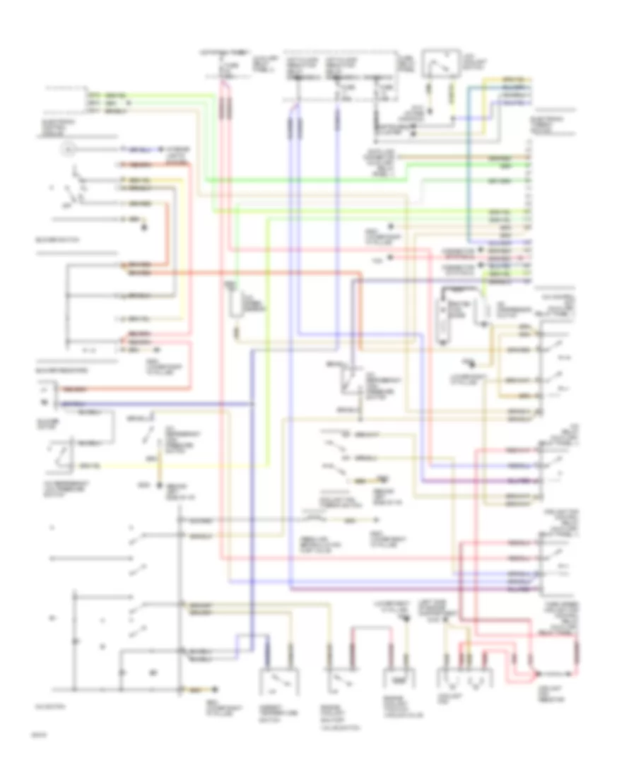
A/C-Heater System Wiring Diagram (100 CS Wiring Diagram 1 Of 2) for Audi 100 CS Quattro 1993

List of elements for A/C-Heater System Wiring Diagram (100 CS Wiring Diagram 1 Of 2) for Audi 100 CS Quattro 1993:
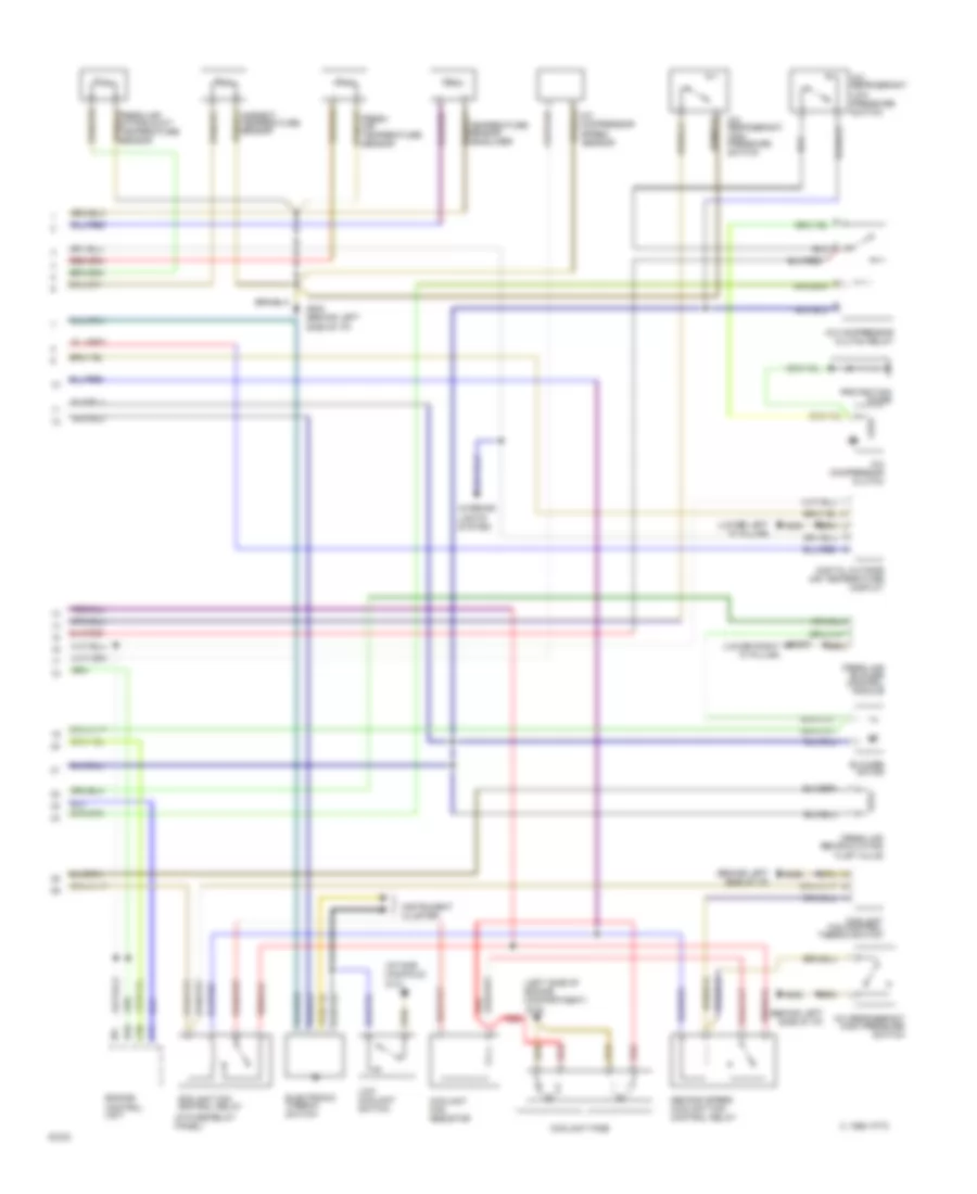
A/C-Heater System Wiring Diagram (100 CS Wiring Diagram 2 Of 2) for Audi 100 CS Quattro 1993
List of elements for A/C-Heater System Wiring Diagram (100 CS Wiring Diagram 2 Of 2) for Audi 100 CS Quattro 1993:
Manual A/C Wiring Diagram for Audi 100 CS Quattro 1993
List of elements for Manual A/C Wiring Diagram for Audi 100 CS Quattro 1993: