AIR CONDITIONING
Automatic A/C Wiring Diagram (1 of 3) for Audi A3 Premium Plus Quattro 2013

List of elements for Automatic A/C Wiring Diagram (1 of 3) for Audi A3 Premium Plus Quattro 2013:
- (behind left kick panel) g44
- (behind right kick panel) g638
- (in engine compt, on a/c high pressure line) high pressure sensor
- (in right plenum chamber) air quality sensor
- 16a
- 22a
- 37a
- A/c compressor regulator valve (rear of a/c compressor)
- Climatronic control module
- Evaporator vent temperature sensor (right front of center console)
- Fresh air blower (under right side of dash)
- Fresh air blower control module (below right side of dash)
- Fuse 10a
- Fuse 20a
- Fuse 40a
- Fuse 5a
- Fuse panel c (under left side of dash)
- G638 (behind right kick panel)
- Hot at all times
- Left footwell vent temperature sensor (left side of hvac unit)
- Left temperature flap motor & potentiometer/ actuator (left side of hvac unit)
- Nca
- Red
- Right footwell vent temperature sensor (top right side of hvac unit)
- Seats system
- T10a
- T16d
- T20j
- W/ heated seats
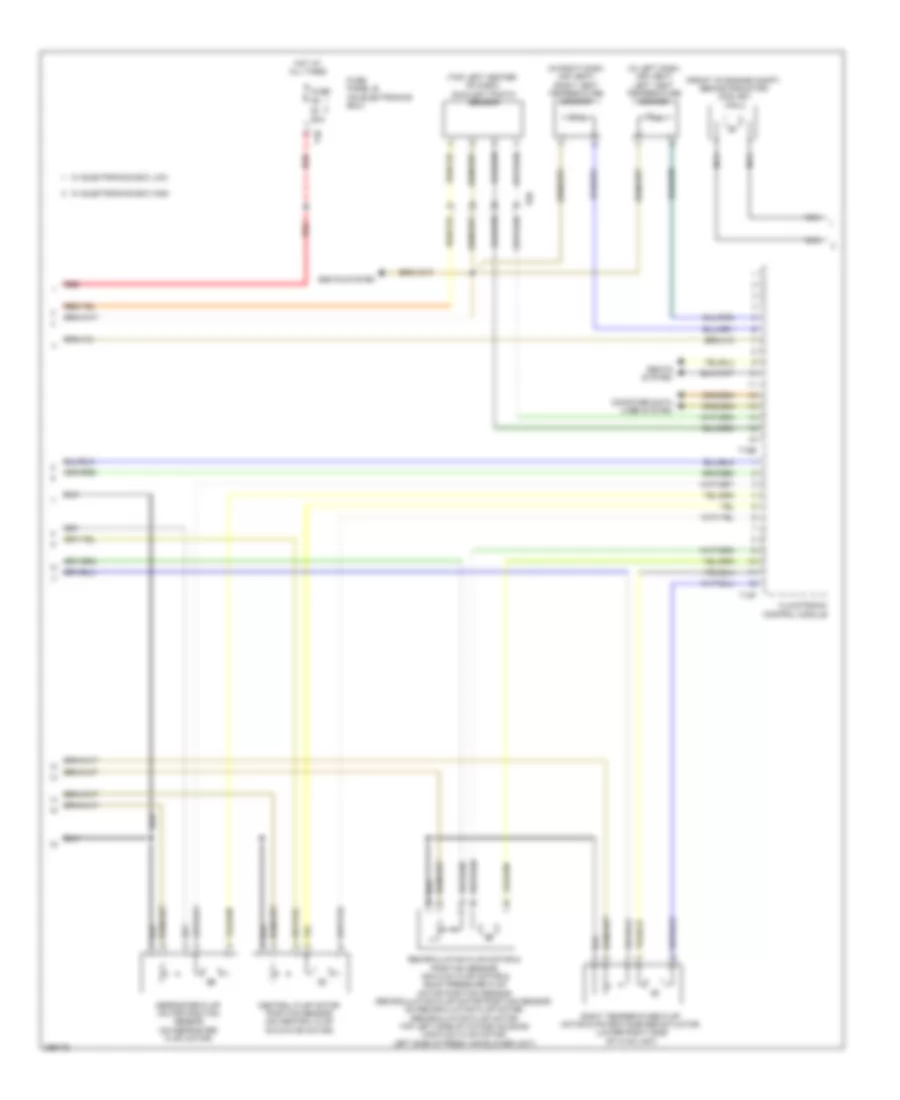
Automatic A/C Wiring Diagram (2 of 3) for Audi A3 Premium Plus Quattro 2013
List of elements for Automatic A/C Wiring Diagram (2 of 3) for Audi A3 Premium Plus Quattro 2013:
- (front of engine compt, behind radiator) coolant fan 2
- (in left dash air vent) left vent temperature sensor
- (in right dash air vent) right vent temperature sensor
- (top left center of dash) sunlight photo sensor
- 50a
- Central flap motor position sensor (on central flap actuator motor)
- Climatronic control module
- Computer data lines system
- Defroster flap motor position sensor (on defroster flap motor)
- Fuse
- Fuse panel b (on electronics box)
- Hot at all times
- Nca
- Recirculation flap motor & position sensor, air flow flap motor & back pressure flap motor position sensor (recirculation flap motor position sensor: on recirculation flap motor) (recirculation flap motor: top left side of intake housing) (air flow flap motor: left side of fresh air blower unit)
- Red
- Right temperature flap motor & potentiometer/actuator (lower right side of hvac unit)
- Seats system
- T12f
- T16e
- T40
- T8d
- W/ electronics box high
- W/ electronics box low
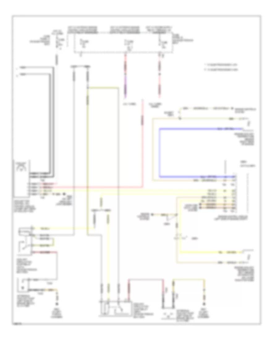
Automatic A/C Wiring Diagram (3 of 3) for Audi A3 Premium Plus Quattro 2013
List of elements for Automatic A/C Wiring Diagram (3 of 3) for Audi A3 Premium Plus Quattro 2013:
- 10a
- 2.0l turbo
- 2.0l turbo diesel
- After-run coolant pump (left side of engine, below oil filter)
- Cbea
- Cbfa
- Ccta
- Ccta & cbfa
- Computer data lines system
- Coolant circulation pump relay (cbfa) (on electronics box high)
- Coolant circulation pump relay (ccta) (on electronics box high)
- Coolant fan
- Coolant fan control (fc) control module (lower left rear of coolant fan)
- Engine control module (left side of engine compt)
- Engine controls system
- Engine coolant temperature (ect) sensor (on radiator) (on lower radiator hose)
- Engine coolant temperature sensor (right rear of engine)
- Except cbfa
- Fuse
- Fuse 15a
- Fuse 50a
- Fuse 5a
- Fuse panel a (on electronics box)
- Fuse panel b (on electronics box)
- G607 (in left plenum chamber)
- G655 (on left headlight long member)
- Hot at all times
- Nca
- T14
- T2az
- T2e
- T40
- T4d
- T60
- T94
- W/ electronics-box high
- W/ electronics-box low