SHIFT INTERLOCK
Shift Interlock Wiring Diagram for Audi A3 Premium Plus Quattro 2013
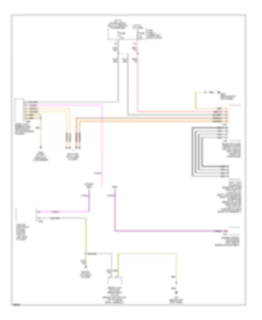
List of elements for Shift Interlock Wiring Diagram for Audi A3 Premium Plus Quattro 2013:
- 14a
- Brake light switch & brake pedal switch (brake light switch: top of brake pedal assembly)
- Cbfa
- Computer data lines system
- Direct shift gearbox (dsg) mechatronic (on transmission housing)
- Engine control module (ecm) (left side of engine compartment)
- Engine controls system
- Except cbfa
- Fuse 10a
- Fuse panel c (under left side of dash)
- G44 (behind left kick panel)
- G638 (behind right kick panel)
- G655 (on left headlight long member)
- Hot at all times
- Nca
- Selector lever sensor system control module (left side of selector lever base)
- Shift lock solenoid & selector lever park position lock switch (shift lock solenoid: front of selector lever base) (selector lever park position lock switch: forward of gear selector assembly)
- T10k
- T20e
- T4r
- T52c
- T94
- Vehicle electrical system control module (left end of dash)
 English